Skip to product information
1 of 3

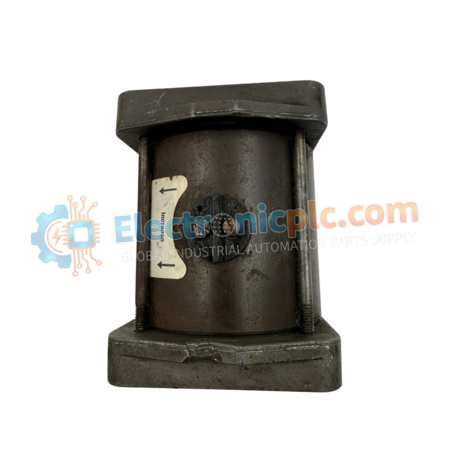
Woodward 8256-016 Electrically Powered Governor Actuator

Woodward 8256-016 Electrically Powered Governor Actuator

The Woodward 8256-016, also cataloged as the 8256-016 Actuator, operates as a dedicated hardware component for rotary fuel control and mechanical throttle positioning within Electrically Powered Governor (EPG) speed control...

20 people are viewing this right now

AvailabilityLow stock: 6 left

SKU: 8256-016
Vendor: Woodward

Shipping & Returns

Reliable Worldwide Delivery

  • Carriers: Shipped via DHL, FedEx, UPS, or USPS.
  • Dispatch: Orders processed in 1-2 business days and dispatched within 3-5 business days.
  • Tracking: Full tracking details provided via email upon shipment.

30-Day Money-Back Guarantee

  • Guarantee: 30-day return window for in-stock, factory-sealed products.
  • Condition: Items must be unopened, unused, and in original packaging.
  • Authenticity: We guarantee 100% original and authentic hardware.

Need more details? Read our fullShipping PolicyandRefund Policy.

Authenticity & Warranty

  • Genuine Guarantee: We supply only 100% original, brand-new, and factory-sealed industrial automation parts.
  • Full Coverage: Every component is backed by a 12-month comprehensive warranty from the date of purchase.
  • Traceability: All products come with original factory documentation and accessories for full industrial compliance.

Technical Support & Sourcing

  • Expert Assistance: Our technical team provides free consultation to help you verify compatibility for DCS and PLC systems.
  • Rare Part Sourcing: Specializing in obsolete and hard-to-find components from Allen-Bradley, Siemens, ABB, HIMA, and more.
  • Bulk Inquiries: Contact us at pambo@5gplc.com for volume pricing or customized project quotes.
View full product details

The Woodward 8256-016, also cataloged as the 8256-016 Actuator, operates as a dedicated hardware component for rotary fuel control and mechanical throttle positioning within Electrically Powered Governor (EPG) speed control systems.

Hardware Specifications

Parameter Specification
Model 8256-016
Brand Woodward
Origin USA
Weight 3kg
Dimensions Standard Compact Profile
Operating Temp -40 to +93 deg C (-40 to +200 deg F)
Power Consumption 95 W maximum
Operating Voltage 24 VDC (20 VDC minimum to 32 VDC maximum)
Output Shaft 0.375 inch - 36 SAE serrated shaft on each end
Maximum Work Output Up to 2.3 J (1.7 ft-lb)
Steady State Speed Band +/-0.25 percent of rated speed
Idle Speed Adjustment 25 percent to 100 percent of rated speed via 50 kohm potentiometer
Magnetic Pickup Requirement Minimum 1.5 Vrms during cranking (typically 100 Hz)
Electrical Protection Requirements 10 A slow-blow fuse or circuit breaker in non-grounded battery lead
Battery Charger Requirement Minimum 5 A continuous supply when energized

Actuator Loop Feedback & Thermal Response

The drive architecture utilizes a 24 VDC electromagnetic coil assembly designed to provide precise mechanical positioning for diesel, gas, and gasoline prime movers. Actuator loop feedback response directly determines dynamic governing stability, maintaining steady-state shaft positions within +/-0.25 percent under load variations. High ambient operational capability up to +93 deg C relies on natural conduction through mounting points, demanding uniform thermal heat sink dissipation across the engine frame or skid mounting interface to prevent heat accumulation during maximum work output conditions (2.3 J).

Frequently Asked Questions

  • Q: What sizing criteria apply to the power source supplying this actuator?
  • A: The auxiliary battery charger or power unit must supply a continuous current of at least 5 A when energized, backed by a 10 A slow-blow fuse or dedicated circuit breaker installed on the non-grounded battery lead.
  • Q: What is the signal threshold required from the magnetic pickup sensor?
  • A: The system requires a minimum signal of 1.5 Vrms generated during engine cranking, typically occurring at a minimum frequency of 100 Hz, to establish a stable speed control feedback loop.
  • Q: What input component modifies the idle speed setting?
  • A: Idle speed adjustments between 25 percent and 100 percent of the rated operational speed are set using an externally connected 50 kohm potentiometer interface.

Field Installation Guidelines

  • Verify that the physical mounting surface acts as an adequate thermal heat sink, ensuring operating temperatures remain below +93 deg C under full electrical load.
  • Install a 10 A slow-blow fuse or equivalent circuit protection device directly into the positive (non-grounded) DC supply line prior to energizing the actuator.
  • Ensure output shaft linkage connects without mechanical binding or excessive radial slop to preserve transient governor response characteristics.
  • Ground all control wiring shielding at a single point to prevent ground loops from degrading magnetic pickup signal accuracy.