
My Cart
0 items
Genuine Automation Parts | Worldwide Express Delivery | 12-Month Warranty — [GET A QUOTE]

Configured for fault-tolerant contact state monitoring and real-time event logging across turbine control system architectures, the WOODWARD 9905-971 Rev(L) (9905-971 Rev(L) Discrete Input Module) provides direct physical/electrical execution.
Availability: Low stock: 6 left
Reliable Worldwide Delivery
30-Day Money-Back Guarantee
Need more details? Read our fullShipping PolicyandRefund Policy.


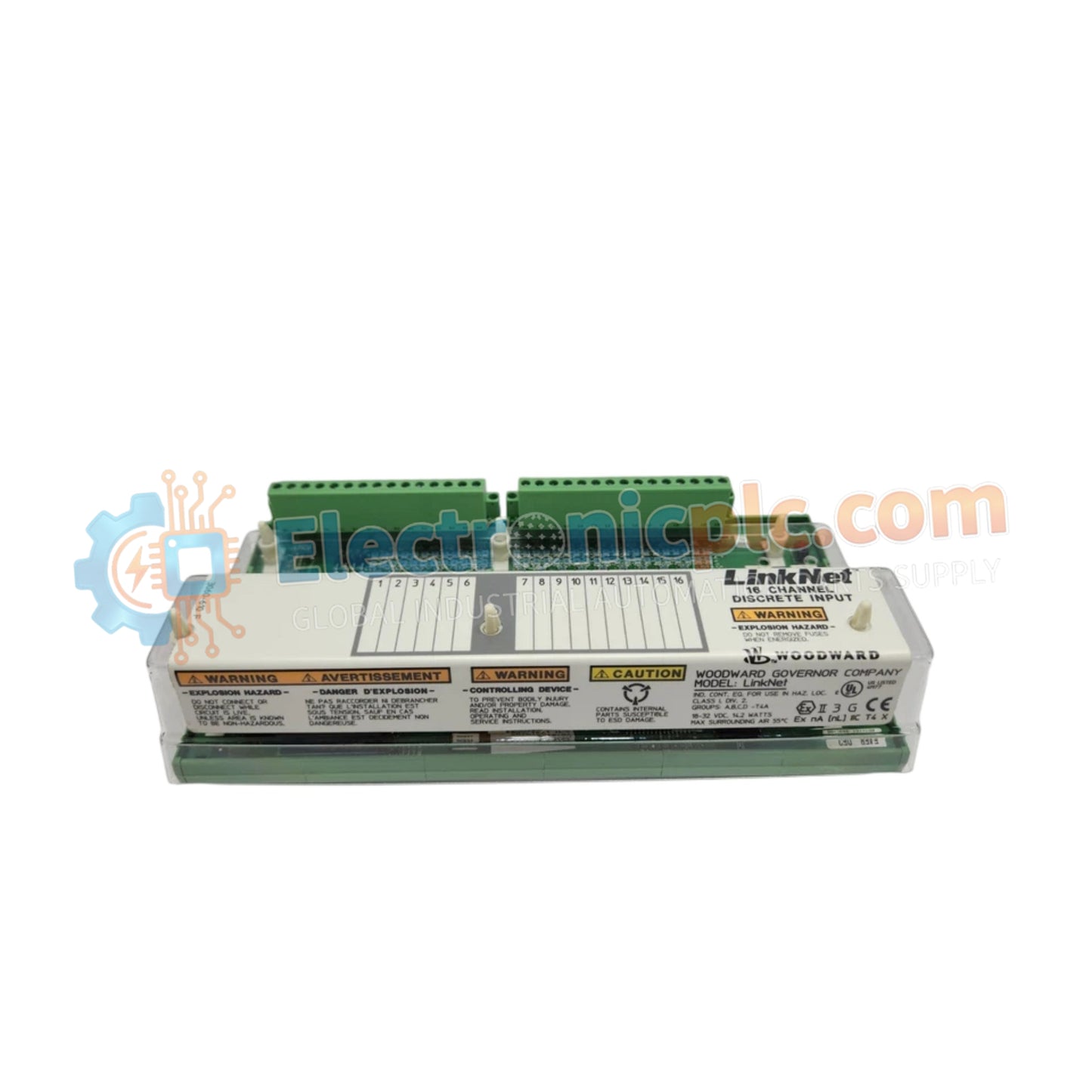
Configured for fault-tolerant contact state monitoring and real-time event logging across turbine control system architectures, the WOODWARD 9905-971 Rev(L) (9905-971 Rev(L) Discrete Input Module) provides direct physical/electrical execution.
| Parameter | Specification |
|---|---|
| Model | 9905-971 Rev(L) |
| Brand | WOODWARD |
| Origin | USA |
| Weight | 1.45kg |
| Dimensions | Standard LinkNet module enclosure |
| Operating Temp | -40 to 85 deg C (-40 to +185 deg F) |
| Power Consumption | 24 VDC nominal wetting power |
| Input Channels | 24 discrete inputs (isolated) |
| Scan Update Time | 5 ms |
| Time Stamping | 1 ms resolution |
| Relay Configurations | 6 redundant output relays with latent fault readback |
The module processes 24 isolated discrete input signals at a rapid 5 ms update rate with 1 ms time-stamping resolution. Onboard readback circuitry executes continuous latent fault detection across relay pairs without disrupting output control states, optimizing system fault-tolerance and actuator loop feedback response. Integral power conversion circuits distribute thermal energy evenly across internal heat sink dissipation profiles, ensuring long-term operational stability within high-density control cabinets.
Q: How does the latent fault detection logic test relay outputs without interrupting system control?
A: Integrated readback circuitry cycles relay contact pairs and verifies physical state transitions. If an incorrect state or contact welding is detected, the diagnostic circuit reports an error and halts further testing without altering the active control output state.
Q: What grounding procedure is required for the fully isolated 24 VDC contact wetting inputs?
A: Because each discrete input circuit is galvano-isolated, a common DC reference potential must be established between the 24 VDC wetting supply and the input group common terminals to prevent floating voltage errors.


