Skip to product information
1 of 3

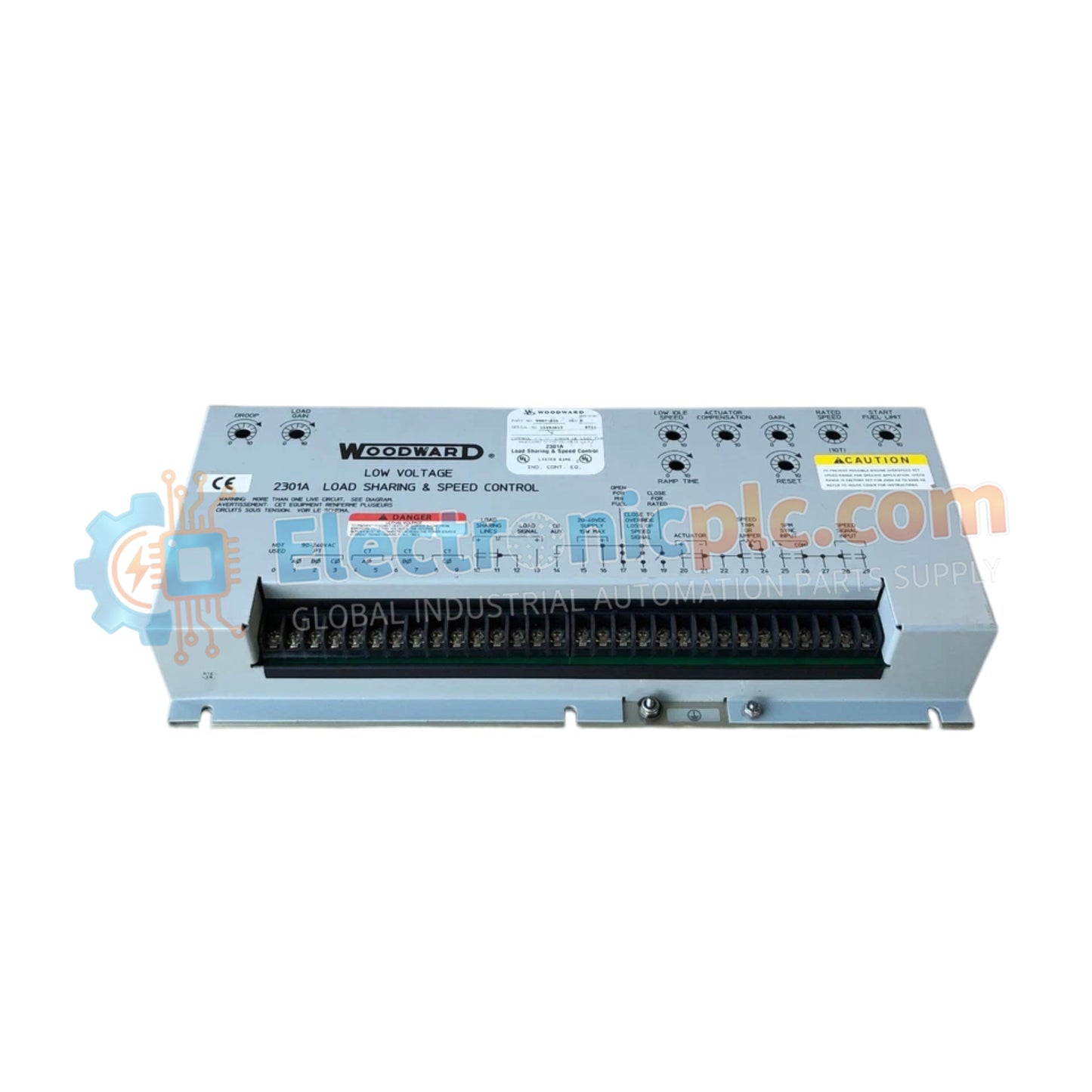
Woodward 9907-018 2301A Load Sharing and Speed Control

Woodward 9907-018 2301A Load Sharing and Speed Control

The Woodward 9907-018, also cataloged as the 9907-018 Speed Control Module, operates as a dedicated hardware component for prime mover speed regulation and proportional load distribution within 2301A Load Sharing...

26 people are viewing this right now

AvailabilityLow stock: 6 left

SKU: 9907-018 2301A
Vendor: Woodward

Shipping & Returns

Reliable Worldwide Delivery

  • Carriers: Shipped via DHL, FedEx, UPS, or USPS.
  • Dispatch: Orders processed in 1-2 business days and dispatched within 3-5 business days.
  • Tracking: Full tracking details provided via email upon shipment.

30-Day Money-Back Guarantee

  • Guarantee: 30-day return window for in-stock, factory-sealed products.
  • Condition: Items must be unopened, unused, and in original packaging.
  • Authenticity: We guarantee 100% original and authentic hardware.

Need more details? Read our fullShipping PolicyandRefund Policy.

Authenticity & Warranty

  • Genuine Guarantee: We supply only 100% original, brand-new, and factory-sealed industrial automation parts.
  • Full Coverage: Every component is backed by a 12-month comprehensive warranty from the date of purchase.
  • Traceability: All products come with original factory documentation and accessories for full industrial compliance.

Technical Support & Sourcing

  • Expert Assistance: Our technical team provides free consultation to help you verify compatibility for DCS and PLC systems.
  • Rare Part Sourcing: Specializing in obsolete and hard-to-find components from Allen-Bradley, Siemens, ABB, HIMA, and more.
  • Bulk Inquiries: Contact us at pambo@5gplc.com for volume pricing or customized project quotes.
View full product details

The Woodward 9907-018, also cataloged as the 9907-018 Speed Control Module, operates as a dedicated hardware component for prime mover speed regulation and proportional load distribution within 2301A Load Sharing and Speed Control systems.

Hardware Specifications

Parameter Specification
Model 9907-018
Brand Woodward
Origin USA
Weight 1.758 kg
Dimensions 15.25 in W x 7.125 in H x 2.5 in D
Operating Temp Standard Industrial Range (-40 to +85 deg C storage)
Power Consumption 15 W or less
Series 2301A Series
Operating Voltage 20 to 40 VDC
Output Current Signal 0 to 200 mA
Certifications CE-marked (EU Low Voltage and EMC Directives), CSA certified for ordinary locations

Actuator Loop Feedback & Harmonic Distortion Suppression

The 2301A module drives hydraulic or electric fuel actuators by converting speed errors and load sharing signals into a calibrated 0 to 200 mA output current. Actuator loop feedback response directly determines dynamic governing performance under rapid step-load transients. Integrated signal conditioning limits high-frequency noise interference, providing harmonic distortion suppression across the magnetic pickup input circuit to preserve steady-state frequency control.

Frequently Asked Questions

  • Q: What cable type should be used for connecting the magnetic speed sensor?
  • A: Magnetic pickup connections require two-conductor twisted-shielded cable to maintain signal integrity, with the cable shield grounded solely at the control unit chassis.
  • Q: How is power supply isolation handled for the 20 to 40 VDC input terminals?
  • A: Operating power must be routed through dedicated fused conductors, keeping DC negative isolated from earth ground unless explicitly required by local system wiring schematics.
  • Q: What is the function of the 0 to 200 mA current output interface?
  • A: The 0 to 200 mA current loop interfaces directly with Woodward fluid/fuel actuator coils to translate electronic speed correction commands into physical valve positioning.

Field Installation Guidelines

  • Mount the unit vertically inside an enclosure using all four mounting holes to maintain stable thermal dissipation across the baseplate.
  • Route signal lines, magnetic pickup wiring, and load-sharing bus cables in separate grounded metallic conduits away from heavy AC power leads.
  • Ensure shield drain wires are connected strictly to the designated chassis terminal to avoid creating unwanted ground potential loops.
  • Verify input voltage remains strictly within the 20 to 40 VDC range under both static and dynamic generator operating states.