
My Cart
0 items
Genuine Automation Parts | Worldwide Express Delivery | 12-Month Warranty — [GET A QUOTE]

Configured for high-speed rotational speed monitoring and emergency shutdown execution in turbine protection networks, the Woodward 9907-345 (9907-345 Overspeed Trip Device) provides direct physical/electrical execution. The hardware continuously monitors prime...
Availability: Low stock: 6 left
Reliable Worldwide Delivery
30-Day Money-Back Guarantee
Need more details? Read our fullShipping PolicyandRefund Policy.


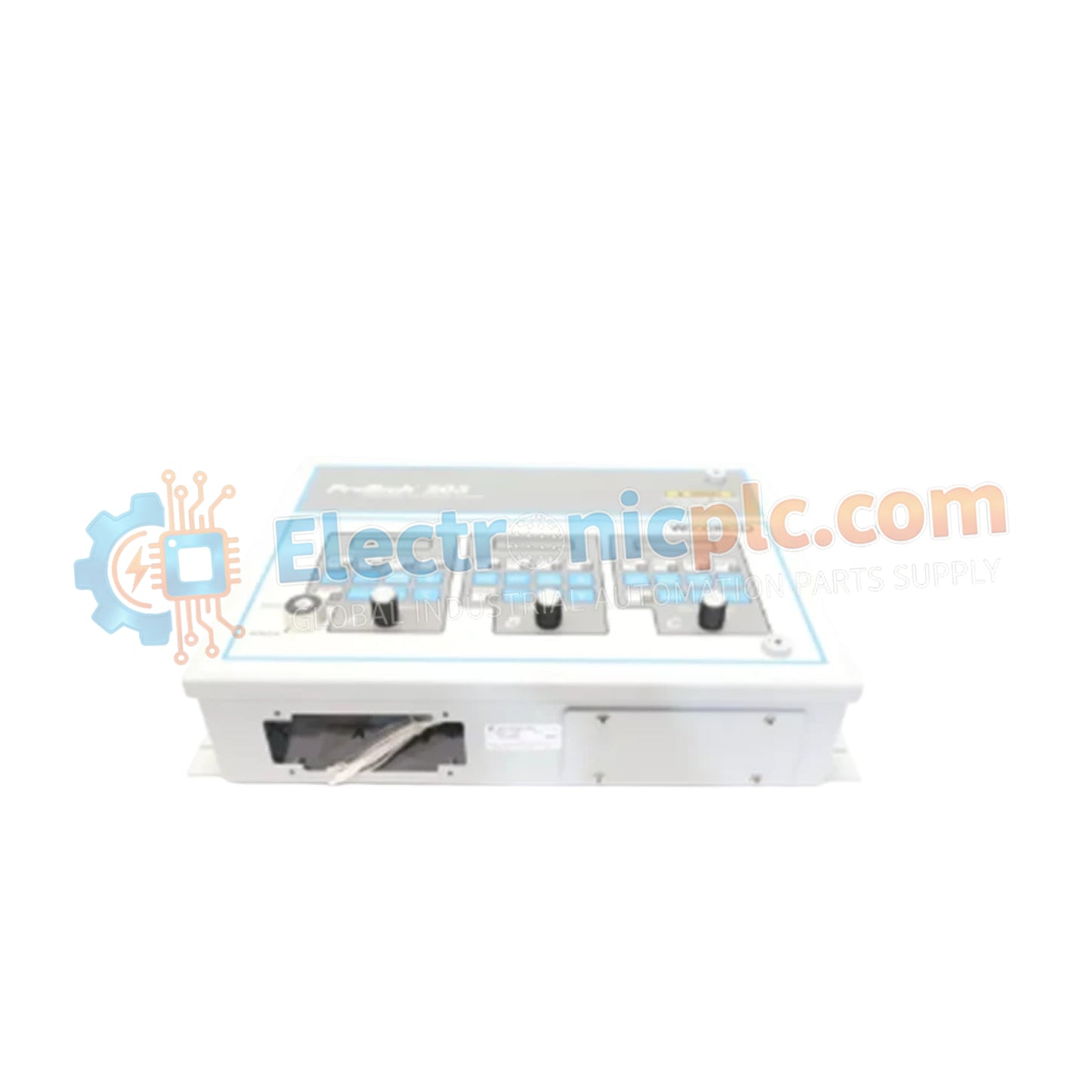
Configured for high-speed rotational speed monitoring and emergency shutdown execution in turbine protection networks, the Woodward 9907-345 (9907-345 Overspeed Trip Device) provides direct physical/electrical execution. The hardware continuously monitors prime mover shaft velocity via magnetic pickup sensors, driving immediate trip relay activation to cut fuel supply upon detecting speed values exceeding pre-programmed safety thresholds.
| Parameter | Specification |
|---|---|
| Model | 9907-345 |
| Brand | Woodward |
| Origin | USA |
| Weight | 3.2 kg |
| Dimensions | 17.8 cm x 19.1 cm x 19.7 cm |
| Operating Temp | -40 deg C to +70 deg C |
| Power Consumption | Standard 24 VDC Control Loop Power |
| Product Type | Overspeed Trip Devices |
| Functional Core | Microprocessor-Based Speed Protection |
| Sensor Inputs | Magnetic Speed Pickup Inputs |
| Output Stage | High-Speed Emergency Trip Relays |
The overspeed protection module utilizes high-speed frequency decoding algorithms to optimize actuator loop feedback response during critical load rejection events. Upon detecting an acceleration rate or absolute velocity crossing the emergency trip limit, the device executes trip contact state changes in under 15 ms. This rapid output response de-energizes trip solenoids and fuel stop valves instantly, preventing catastrophic mechanical overspeed damage and restoring the system to a fail-safe state.
Q: How does the device prevent false trips caused by electrical noise on the speed pickup lines?
A: The input channels incorporate high-frequency noise filtering and variable-threshold peak detection circuits, ensuring only true gear-tooth signal transitions trigger speed calculation logic.
Q: What is the trip contact execution time when an overspeed event occurs?
A: The onboard micro-controller and high-speed output relays process trip state conditions and drop relay contacts in less than 15 ms from signal threshold breach.
Q: Is external power required to maintain protective speed monitoring function?
A: The device requires a continuous 24 VDC auxiliary power supply to drive processing circuits and internal trip relay coils in an energized-to-run configuration.


