
My Cart
0 items
Genuine Automation Parts | Worldwide Express Delivery | 12-Month Warranty — [GET A QUOTE]

The WOODWARD TUG-416 8441-1013, also cataloged as the 8441-1013 Temperature Control Module, operates as a dedicated hardware component for multi-channel thermal monitoring and dynamic actuator loop positioning within turbomachinery control...
Availability: Low stock: 6 left
Reliable Worldwide Delivery
30-Day Money-Back Guarantee
Need more details? Read our fullShipping PolicyandRefund Policy.

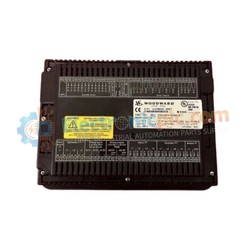
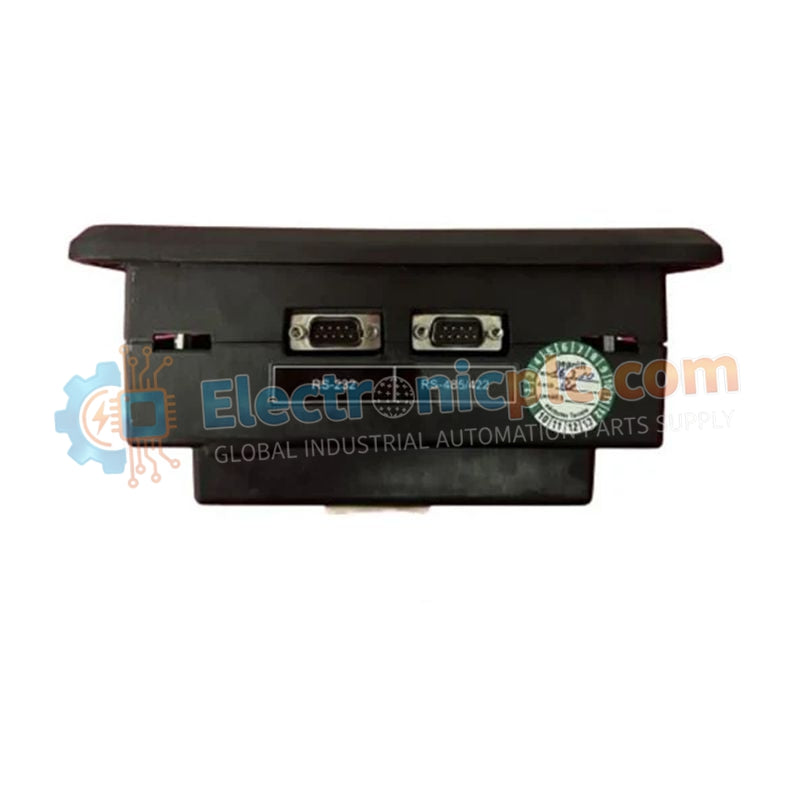
The WOODWARD TUG-416 8441-1013, also cataloged as the 8441-1013 Temperature Control Module, operates as a dedicated hardware component for multi-channel thermal monitoring and dynamic actuator loop positioning within turbomachinery control networks.
| Parameter | Specification |
|---|---|
| Model | TUG-416 8441-1013 |
| Brand | WOODWARD |
| Origin | USA |
| Weight | 2kg |
| Dimensions | Standard |
| Operating Temp | -40 to 85 deg C |
| Power Consumption | 24 VDC |
| Processor | Power Architecture dual-core CPU, 500 MHz |
| Memory | 1 MB SRAM cache |
| Analog Inputs | 32 analog inputs (e.g., Pt100 temperature sensors) |
| Digital Outputs | 16 digital outputs |
| Output Signal | 4-20 mA (< 1 ms response time) |
| Communication Interfaces | Dual Ethernet (Modbus TCP/IP), isolated RS-485, CAN 2.0B, Profibus-DP (optional) |
The dual-core 500 MHz Power Architecture processor samples 32 analog channels with a sub-millisecond response time (< 1 ms), converting RTD and 4-20 mA signals into high-speed control variables. The processing core calculates closed-loop thermal limits to adjust actuator loop feedback response under severe transient conditions. Internal power conditioning circuits direct thermal heat dissipation through the module frame, preventing local thermal drift across high-density analog-to-digital conversion stages.
Q: How does the dual-core CPU execute fault detection and system redundancy?
A: The onboard dual-core CPU features integrated hardware watchdogs and automated fault recording logic, continuously cross-checking memory and execution pipelines to trigger fail-safe states upon detecting system anomalies.
Q: What communication protocols are supported over the onboard network interfaces?
A: The module includes dual Ethernet ports running Modbus TCP/IP, an isolated RS-485 serial port, a CAN 2.0B bus interface, and optional Profibus-DP connectivity for integration with main plant networks.


