
My Cart
0 items
Genuine Automation Parts | Worldwide Express Delivery | 12-Month Warranty — [GET A QUOTE]

Configured for high-speed signal propagation in Yokogawa CENTUM control networks, the YOKOGAWA YCB301-C200 (YCB301 ESB Bus Cable) provides direct physical data link execution between Field Control Units (FCUs) and Advanced...
Availability: In stock
Reliable Worldwide Delivery
30-Day Money-Back Guarantee
Need more details? Read our fullShipping PolicyandRefund Policy.


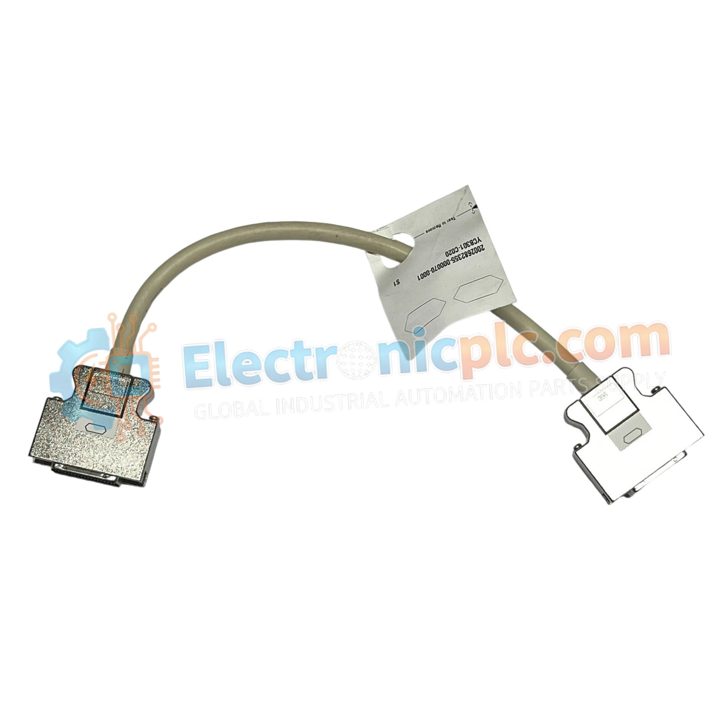
Configured for high-speed signal propagation in Yokogawa CENTUM control networks, the YOKOGAWA YCB301-C200 (YCB301 ESB Bus Cable) provides direct physical data link execution between Field Control Units (FCUs) and Advanced Network Bus (ANB) node units.
| Model | Suffix Code | Description |
|---|---|---|
| YCB301 | -C200 | ESB Bus Cable, 36-36 pin configuration, 2 meters length |
| Parameter | Specification |
|---|---|
| Model | YCB301-C200 |
| Brand | YOKOGAWA |
| Origin | Japan |
| Weight | 2 kg |
| Dimensions | 2 meters length |
| Operating Temp | -20 deg C to 70 deg C |
| Power Consumption | N/A (Passive interconnect) |
| Connector Type | 36-pin to 36-pin interface |
| Compatibility | ESB Bus (FCU to ANB node) |
The YCB301-C200 functions as a shielded interconnect medium within the ESB bus architecture. To ensure deterministic network performance, the cable assembly incorporates specific pin-to-pin wiring for 36-pin interface ports, minimizing signal attenuation during data transfer between control controllers and remote I/O nodes. The physical shielding layer is engineered to mitigate electromagnetic interference, maintaining the signal-to-noise ratio necessary for Yokogawa control platform communication protocols.
Q: Can this cable be extended using standard couplers or signal boosters?
A: No, extending the physical length of the ESB bus cable beyond manufacturer specifications is not permitted. Signal timing constraints within the ESB network may be violated, leading to bus communication errors or node timeouts.
Q: What are the primary grounding requirements for the YCB301-C200?
A: The cable must be routed through dedicated cable trays to ensure proper shield continuity. Ensure that the 36-pin connectors are fully seated and that the integrated locking clips are engaged to maintain a consistent chassis ground reference.


