
My Cart
0 items
Genuine Automation Parts | Worldwide Express Delivery | 12-Month Warranty — [GET A QUOTE]

The YOKOGAWA YNT511D-V42/KT, also cataloged as the YNT511D Optical Bus Repeater, operates as a dedicated hardware component for signal amplification and transmission distance extension within CENTUM VP and CENTUM CS...
Availability: In stock
Reliable Worldwide Delivery
30-Day Money-Back Guarantee
Need more details? Read our fullShipping PolicyandRefund Policy.


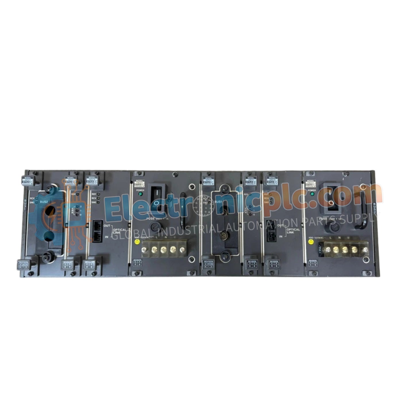
The YOKOGAWA YNT511D-V42/KT, also cataloged as the YNT511D Optical Bus Repeater, operates as a dedicated hardware component for signal amplification and transmission distance extension within CENTUM VP and CENTUM CS optical ESB bus networks.
| Parameter | Specification |
|---|---|
| Model | YNT511D-V42/KT |
| Brand | YOKOGAWA |
| Origin | Japan |
| Weight | 3.6 kg |
| Dimensions | 48.3 cm x 17.8 cm x 30.5 cm |
| Operating Temp | 0 deg C to 50 deg C |
| Power Consumption | 60 mA (Max) |
| Rack Format | 19-inch standard |
| Module Slots | 13 |
| Isolation Voltage | 1 kV DC |
The YNT511D-V42/KT is engineered to maintain network determinism by providing optical isolation between disparate segments of the ESB bus architecture. By facilitating signal regeneration, the rack prevents data degradation over extended cabling, ensuring consistent throughput across distributed control system nodes. The 1 kV DC isolation voltage serves to decouple the optical repeater circuitry from potential ground loops or electromagnetic surges present in the wider industrial instrumentation infrastructure, supporting the integrity of the CENTUM DCS communication protocol.
Q: Can the 13 slots be populated with different types of repeater modules?
A: Yes, the rack supports mixed-module configurations provided they are compatible with the backplane bus signaling and the CENTUM system requirements. Ensure all installed modules are properly seated to maintain power distribution across the backplane.
Q: What are the primary requirements for the rack's chassis grounding?
A: The rack must be connected to a low-impedance facility earth ground via the rear-mounted grounding lug. This is necessary to satisfy the 1 kV DC isolation specification and provide an effective path for transient electrical noise.


