My Cart
0 items
Genuine Automation Parts | Worldwide Express Delivery | 12-Month Warranty — [GET A QUOTE]

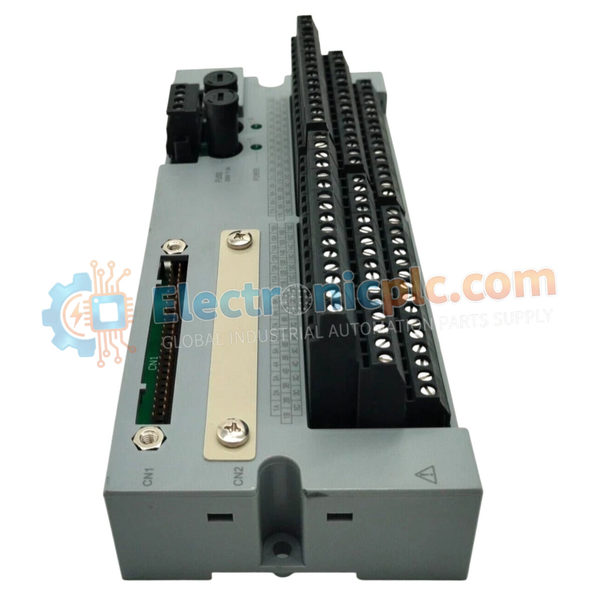
Configured for high-density signal distribution in DCS platforms, the YOKOGAWA A1BD5D-05 (A1BD5D-05 Terminal Board) provides direct physical/electrical execution of field wiring termination for digital I/O modules within CENTUM VP architectures.
...Availability: Low stock: 99 left
Reliable Worldwide Delivery
30-Day Money-Back Guarantee
Need more details? Read our fullShipping PolicyandRefund Policy.

Configured for high-density signal distribution in DCS platforms, the YOKOGAWA A1BD5D-05 (A1BD5D-05 Terminal Board) provides direct physical/electrical execution of field wiring termination for digital I/O modules within CENTUM VP architectures.
| Parameter | Specification |
|---|---|
| Model | A1BD5D-05 |
| Brand | YOKOGAWA |
| Origin | japan |
| Weight | 0.70 kg |
| Dimensions | Standard DIN-rail mount format |
| Operating Temp | Standard Industrial Range |
| Power Consumption | Passive Interface |
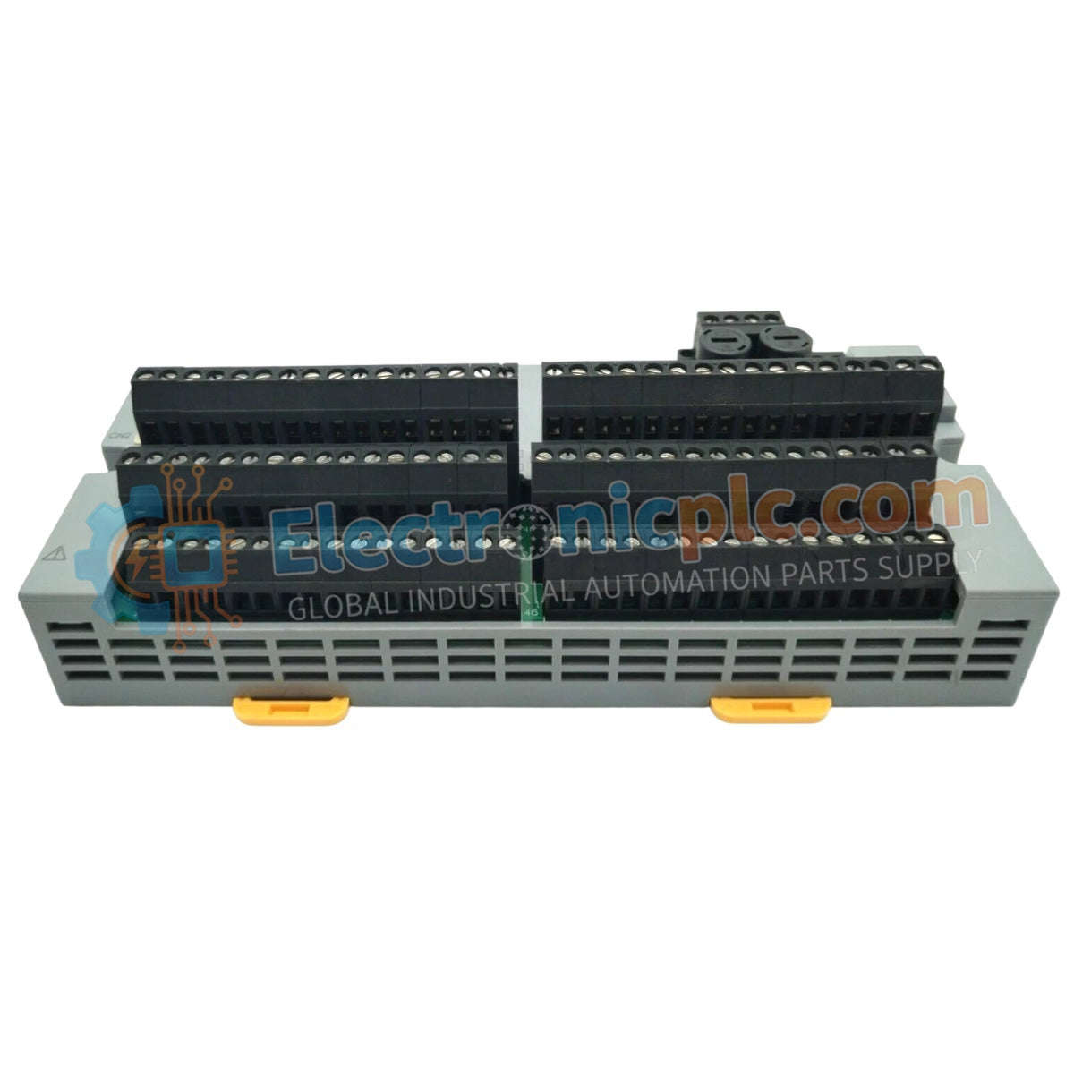
| Channel Capacity | 32 channels x 1 block |
| Terminal Type | Pressure clamp |
| Insulation Resistance | >= 10 MΩ at 500 VDC |
The A1BD5D-05 acts as the physical interface between field-level discrete devices and digital I/O modules. The board supports both single and dual-redundant module configurations, ensuring high-availability signal path management. To maintain signal integrity, the terminal board supports 600 V PVC-insulated wiring and maintains a withstanding voltage of 2.0 kVAC (between power and READY terminals). The board facilitates 24 VDC (+/- 10%) power distribution to connected field loops, providing a compact, DIN-rail mountable solution for space-constrained control cabinets.
Q: Can the A1BD5D-05 be used for analog signal termination?
A: No, this terminal board is engineered specifically for digital I/O channels; utilizing it for analog signal paths may lead to impedance mismatches and signal distortion.
Q: Does the board provide internal fusing for the 32 channels?
A: The A1BD5D-05 acts as a signal pass-through terminal block. External fusing must be implemented according to the specific loop requirements and the protection standards of the field device.


