Skip to product information
1 of 3

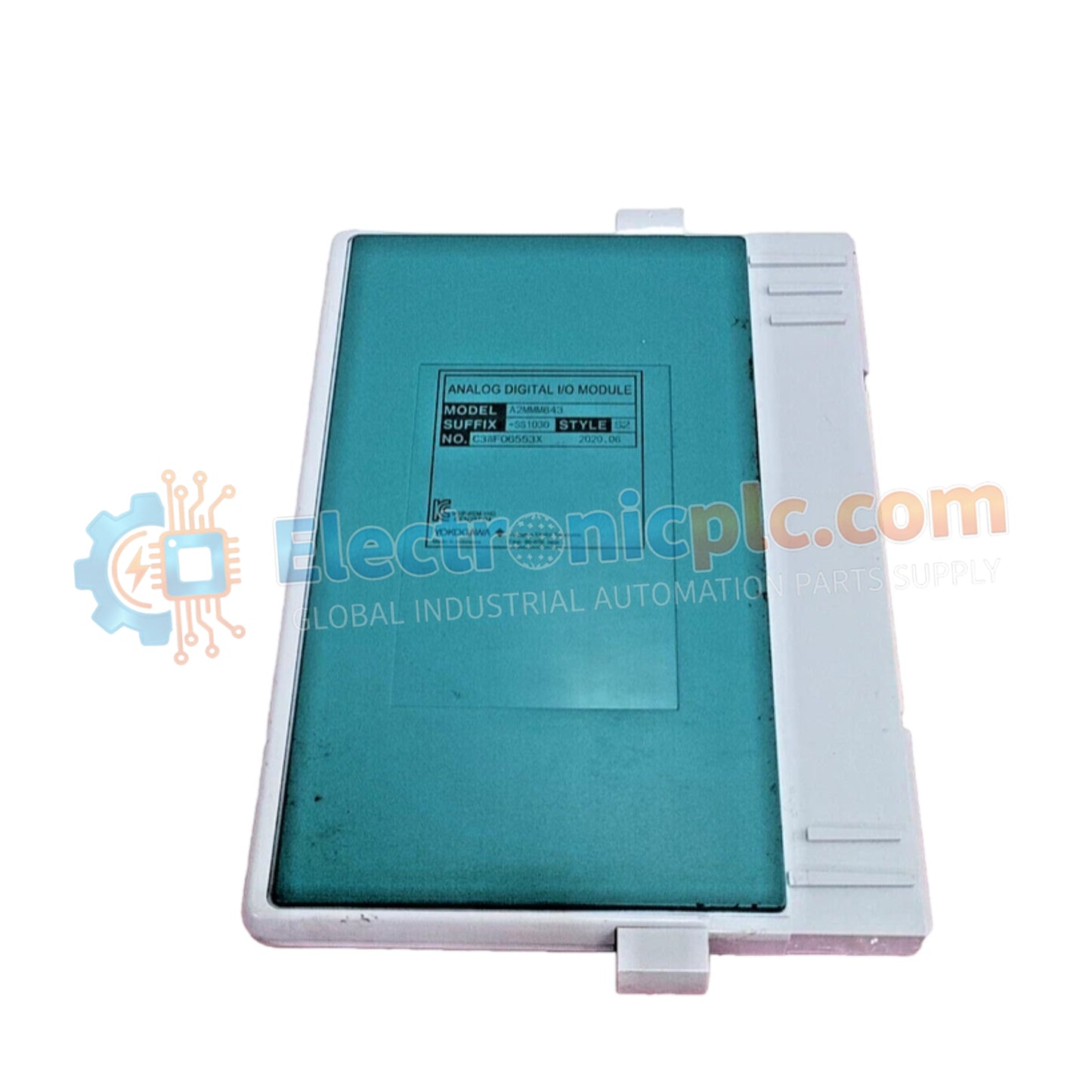
YOKOGAWA A2MMM843-SS1000 Digital I/O Module

YOKOGAWA A2MMM843-SS1000 Digital I/O Module

Configured for high-density signal integration in CENTUM VP N-I/O architectures, the YOKOGAWA A2MMM843-SS1000 (A2MMM843-SS1000 Digital I/O Module) provides direct electrical execution of 16-channel configurable digital input or output operations. The...

28 people are viewing this right now

AvailabilityIn stock

SKU: A2MMM843-SS1000
Vendor: Yokogawa
Category: Digital I/O Module
Related Series:

Shipping & Returns

Reliable Worldwide Delivery

  • Carriers: Shipped via DHL, FedEx, UPS, or USPS.
  • Dispatch: Orders processed in 1-2 business days and dispatched within 3-5 business days.
  • Tracking: Full tracking details provided via email upon shipment.

30-Day Money-Back Guarantee

  • Guarantee: 30-day return window for in-stock, factory-sealed products.
  • Condition: Items must be unopened, unused, and in original packaging.
  • Authenticity: We guarantee 100% original and authentic hardware.

Need more details? Read our fullShipping PolicyandRefund Policy.

Authenticity & Warranty

  • Genuine Guarantee: We supply only 100% original, brand-new, and factory-sealed industrial automation parts.
  • Full Coverage: Every component is backed by a 12-month comprehensive warranty from the date of purchase.
  • Traceability: All products come with original factory documentation and accessories for full industrial compliance.

Technical Support & Sourcing

  • Expert Assistance: Our technical team provides free consultation to help you verify compatibility for DCS and PLC systems.
  • Rare Part Sourcing: Specializing in obsolete and hard-to-find components from Allen-Bradley, Siemens, ABB, HIMA, and more.
  • Bulk Inquiries: Contact us at pambo@5gplc.com for volume pricing or customized project quotes.
View full product details

Configured for high-density signal integration in CENTUM VP N-I/O architectures, the YOKOGAWA A2MMM843-SS1000 (A2MMM843-SS1000 Digital I/O Module) provides direct electrical execution of 16-channel configurable digital input or output operations. The module facilitates versatile signal mapping across hazardous area applications while maintaining compliance with international industrial safety standards.

Suffix Breakdown & Model Matrix

  • A2MMM843: Base model designation for the 16-channel software-selectable digital I/O module.
  • -S: Standard hardware configuration.
  • S1: Revision code indicating hardware compatibility for N-I/O baseboards.
  • 000: Standard firmware and regulatory certification package.

Hardware Specifications

Parameter Specification
Model A2MMM843-SS1000
Brand YOKOGAWA
Origin Japan
Weight 0.41 kg
Dimensions Standard N-I/O module footprint
Operating Temp -20 to 60 deg C
Power Consumption 700 mA (max)
Channel Type 16-channel, software-selectable DI/DO
Isolation 1500 VAC (1 min)
Mounting Baseboard (A2BN4D / A2BN5D)

Channel-to-Channel Isolation and Redundancy

The A2MMM843-SS1000 features galvanic isolation rated at 1500 VAC between I/O channels and the system bus, preventing electrical stress propagation during field faults. The module architecture supports dual-redundant configurations, allowing two modules to operate in parallel to ensure uninterrupted control logic execution. This fault-tolerant design is reinforced by hardware-level diagnostic checks that detect open-loop or short-circuit conditions, facilitating secure operation in IEC Zone 2 and Class I Div. 2 environments.

Frequently Asked Questions

Q: Can channels be reconfigured while the system is running?

A: Yes. The software-selectable nature of the 16 channels allows for dynamic configuration changes through the CENTUM VP engineering environment, provided the safety and control interlocks permit the transition.

Q: Is this module compatible with non-redundant baseboards?

A: Yes, it is physically compatible with A2BN4D and A2BN5D baseboards; however, redundant functionality is strictly dependent on the baseboard's capability to support dual-module communication.

Field Installation Guidelines

  1. Verify that the N-I/O baseboard is de-energized before module insertion to avoid terminal arcing.
  2. Align the module with the slot guides on the A2BN4D/A2BN5D baseboard and apply firm, even pressure until the locking mechanism engages.
  3. Ensure that the module fastening screws are secured to the baseboard chassis to maintain electrical continuity for EMI/RFI shielding.
  4. Route digital field wiring through shielded conduit or cable trays, ensuring separation from high-power circuits to minimize common-mode noise.
  5. Confirm that the channel configuration parameters match the physical wiring at the terminal board prior to activating the I/O loops.