
My Cart
0 items
Genuine Automation Parts | Worldwide Express Delivery | 12-Month Warranty — [GET A QUOTE]

Configured for signal routing within the N-IO system platform, the YOKOGAWA A2SMX801-S130 (A2SMX801-S130 Pass-through I/O Signal Adaptor) provides direct physical execution of I/O signal mapping. The adaptor serves as a...
Availability: In stock
Reliable Worldwide Delivery
30-Day Money-Back Guarantee
Need more details? Read our fullShipping PolicyandRefund Policy.


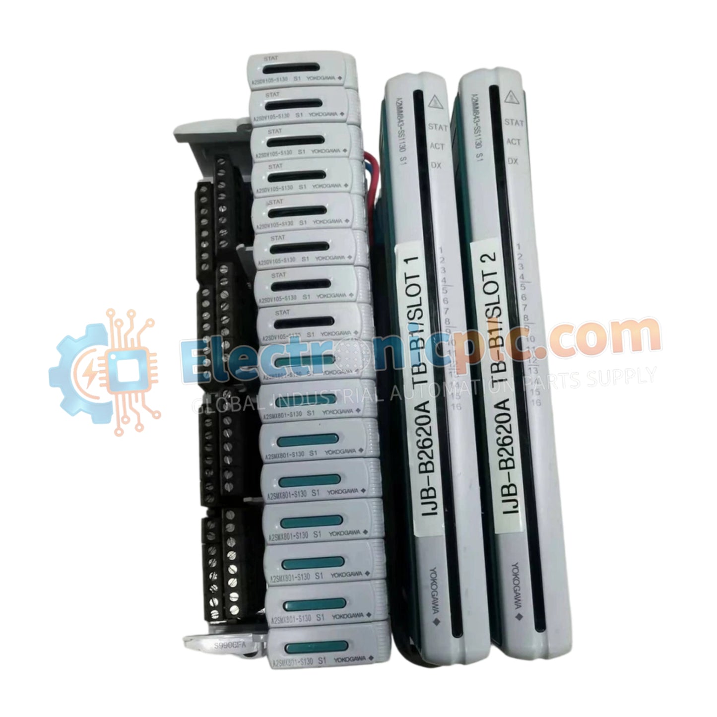
Configured for signal routing within the N-IO system platform, the YOKOGAWA A2SMX801-S130 (A2SMX801-S130 Pass-through I/O Signal Adaptor) provides direct physical execution of I/O signal mapping. The adaptor serves as a passive interface to connect field instruments and sensors directly to the control system, facilitating data acquisition and control without signal conditioning.
| Parameter | Specification |
|---|---|
| Model | A2SMX801-S130 |
| Brand | YOKOGAWA |
| Origin | Not specified |
| Weight | Not specified |
| Dimensions | Standard N-IO module footprint |
| Operating Temp | 0 to 60 deg C |
| Power Consumption | Passive (None) |
| Function | Pass-through I/O signal adaptation |
| Isolation | Non-isolated |
The A2SMX801-S130 operates as a non-isolated signal interface component. It is engineered to maintain low-impedance paths between field transmitters and the N-IO system backplane. Because this unit lacks active galvanic isolation, it is designed for environments where field devices are either self-isolated or where ground loop currents are managed via external secondary protection measures. The adaptor ensures consistent 4-20 mA HART loop protocol connectivity by providing a continuous transmission path for digital and analog signal overlays.
Q: Does this adaptor require external power for operation?
A: No. The A2SMX801-S130 is a passive pass-through device and does not require external power or internal voltage regulation to function.
Q: Can this unit be used as a replacement for isolated signal converters?
A: No. This adaptor provides no galvanic isolation. If the application requires protection against common-mode noise or electrical isolation between the field instrument and the control system, an active signal isolator must be utilized.


