Skip to product information
1 of 3

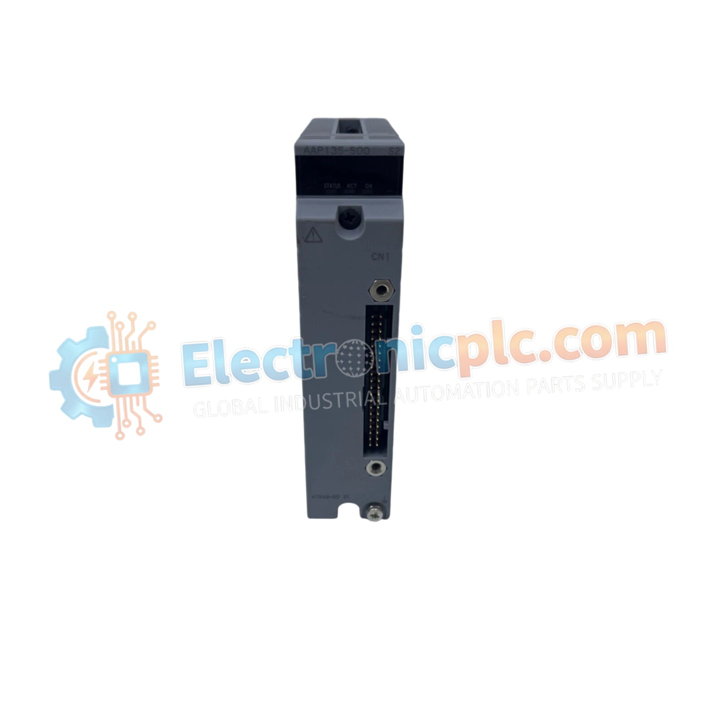
Yokogawa AAP135-S00/I3S00 Pulse Input Module

Yokogawa AAP135-S00/I3S00 Pulse Input Module

The Yokogawa AAP135-S00/I3S00, also cataloged as the AAP135 Pulse Input Module, operates as a dedicated hardware component for high-frequency pulse counting and frequency detection within FIO (Field Control Station) I/O...

29 people are viewing this right now

AvailabilityIn stock

SKU: AAP135-S00/I3S00
Vendor: Yokogawa
Category: Pulse Input Module
Related Series:

Shipping & Returns

Reliable Worldwide Delivery

  • Carriers: Shipped via DHL, FedEx, UPS, or USPS.
  • Dispatch: Orders processed in 1-2 business days and dispatched within 3-5 business days.
  • Tracking: Full tracking details provided via email upon shipment.

30-Day Money-Back Guarantee

  • Guarantee: 30-day return window for in-stock, factory-sealed products.
  • Condition: Items must be unopened, unused, and in original packaging.
  • Authenticity: We guarantee 100% original and authentic hardware.

Need more details? Read our fullShipping PolicyandRefund Policy.

Authenticity & Warranty

  • Genuine Guarantee: We supply only 100% original, brand-new, and factory-sealed industrial automation parts.
  • Full Coverage: Every component is backed by a 12-month comprehensive warranty from the date of purchase.
  • Traceability: All products come with original factory documentation and accessories for full industrial compliance.

Technical Support & Sourcing

  • Expert Assistance: Our technical team provides free consultation to help you verify compatibility for DCS and PLC systems.
  • Rare Part Sourcing: Specializing in obsolete and hard-to-find components from Allen-Bradley, Siemens, ABB, HIMA, and more.
  • Bulk Inquiries: Contact us at pambo@5gplc.com for volume pricing or customized project quotes.
View full product details

The Yokogawa AAP135-S00/I3S00, also cataloged as the AAP135 Pulse Input Module, operates as a dedicated hardware component for high-frequency pulse counting and frequency detection within FIO (Field Control Station) I/O subsystems.

Suffix Breakdown & Model Matrix

  • AAP135: Base model series for 8-channel pulse input modules (0 to 10 kHz).
  • -S: Standard hardware type.
  • 00: Basic configuration variant.
  • /I3S00: Specific option code indicating standard interface connectivity for field wiring and signal conditioning compatibility.

Hardware Specifications

Parameter Specification
Model AAP135-S00/I3S00
Brand Yokogawa
Origin Japan
Weight 0.3 kg
Dimensions 33 mm x 107 mm x 130 mm
Operating Temp -20 deg C to 70 deg C
Power Consumption Backplane bus dependent
Input Channels 8 independent channels
Frequency Range 0 to 10 kHz
Isolation Channel-to-channel isolated

Process Control and Signal Integrity

The AAP135-S00/I3S00 serves as a high-precision interface for rotary encoders, flow meters, and tachometers. The module architecture employs channel-to-channel isolation to prevent ground loop interference, which is critical when processing fast-switching pulse trains in industrial environments. By decoupling the input circuitry from the system bus, the module maintains data fidelity, ensuring accurate pulse accumulation across all 8 channels. Furthermore, the design supports the robust signal handling required for 4-20 mA loop environments where pulse-derived data must be integrated into DCS control strategies without signal degradation.

Frequently Asked Questions

Q: Does the AAP135-S00/I3S00 support hot-swapping during active operation?

A: Yes, the module supports hot-swapping within compliant Yokogawa FIO racks. Ensure the control station software is set to the designated maintenance mode to prevent unexpected pulse count resets or bus interrupts during the module extraction process.

Q: Is external signal conditioning required for low-voltage sensor pulses?

A: The module is designed to accept standard industrial pulse signals. If the sensor output voltage or current does not meet the specified input threshold, an external signal level converter may be required to ensure reliable pulse detection.

Field Installation Guidelines

  • Mounting: Verify the base plate is clean before seating the module. Slide the module into the designated slot until the locking lever clicks, indicating full engagement with the backplane communication pins.
  • Wiring: Use twisted-pair shielded cables to connect field sensors to the module. To optimize signal integrity, ground the cable shield at the cabinet entry point using a high-conductivity ground bar.
  • Grounding: The module chassis must be securely bonded to the cabinet's internal grounding reference to mitigate common-mode noise associated with high-frequency pulse acquisition.
  • Environmental: Maintain ambient operating conditions between -20 deg C and 70 deg C. Avoid mounting the module near heavy power-switching hardware to prevent induced electromagnetic noise on the pulse input lines.