Skip to product information
1 of 3

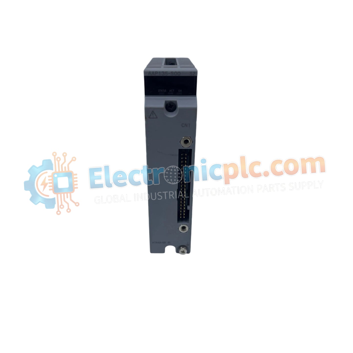
Yokogawa AAP135-S50/K4A00 Pulse Input Module

Yokogawa AAP135-S50/K4A00 Pulse Input Module

The Yokogawa AAP135-S50/K4A00, also cataloged as the AAP135 Pulse Input Module, operates as a dedicated hardware component for high-frequency pulse counting and frequency measurement within FIO (Field Control Station) I/O...

15 people are viewing this right now

AvailabilityIn stock

SKU: AAP135-S50/K4A00
Vendor: Yokogawa
Category: Pulse Input Module
Related Series:

Shipping & Returns

Reliable Worldwide Delivery

  • Carriers: Shipped via DHL, FedEx, UPS, or USPS.
  • Dispatch: Orders processed in 1-2 business days and dispatched within 3-5 business days.
  • Tracking: Full tracking details provided via email upon shipment.

30-Day Money-Back Guarantee

  • Guarantee: 30-day return window for in-stock, factory-sealed products.
  • Condition: Items must be unopened, unused, and in original packaging.
  • Authenticity: We guarantee 100% original and authentic hardware.

Need more details? Read our fullShipping PolicyandRefund Policy.

Authenticity & Warranty

  • Genuine Guarantee: We supply only 100% original, brand-new, and factory-sealed industrial automation parts.
  • Full Coverage: Every component is backed by a 12-month comprehensive warranty from the date of purchase.
  • Traceability: All products come with original factory documentation and accessories for full industrial compliance.

Technical Support & Sourcing

  • Expert Assistance: Our technical team provides free consultation to help you verify compatibility for DCS and PLC systems.
  • Rare Part Sourcing: Specializing in obsolete and hard-to-find components from Allen-Bradley, Siemens, ABB, HIMA, and more.
  • Bulk Inquiries: Contact us at pambo@5gplc.com for volume pricing or customized project quotes.
View full product details

The Yokogawa AAP135-S50/K4A00, also cataloged as the AAP135 Pulse Input Module, operates as a dedicated hardware component for high-frequency pulse counting and frequency measurement within FIO (Field Control Station) I/O subsystems.

Suffix Breakdown & Model Matrix

  • AAP135: Base model series for 8-channel pulse input modules (0 to 10 kHz).
  • -S: Standard hardware type.
  • 5: No explosion protection configuration.
  • 0: Basic functionality variant.
  • /K4A00: Includes integrated KS Cable Interface Adapter (Model: ATK4A-00) for simplified field wiring.

Hardware Specifications

Parameter Specification
Model AAP135-S50/K4A00
Brand Yokogawa
Origin Japan
Weight 0.3 kg
Dimensions Standard FIO Module Form Factor
Operating Temp -20 deg C to 70 deg C
Power Consumption Backplane bus dependent
Input Channels 8 independent channels
Frequency Range 0 to 10 kHz
Isolation Channel-to-channel isolated

Process Control and Signal Integrity

The AAP135-S50/K4A00 is engineered to provide precise pulse counting for flow meters, tachometers, and rotary encoders within process automation environments. By utilizing isolated input channels, the module effectively suppresses common-mode noise and prevents ground loop interference that often compromises pulse-train accuracy in long-distance cabling. The integration with the ATK4A-00 interface adapter facilitates seamless field-to-backplane termination, ensuring that the 0 to 10 kHz signal path maintains high signal-to-noise ratios. This deterministic hardware performance is critical for maintaining accurate pulse accumulation, supporting reliable control and monitoring within the FCS architecture.

Frequently Asked Questions

Q: Does the AAP135-S50/K4A00 support hot-swapping during active operation?

A: Yes. The module supports hot-swapping within FIO-compliant racks. However, ensure the FCS software is in the correct maintenance state to prevent spurious pulse interrupts or loss of count data during the module removal and insertion cycle.

Q: Can this module differentiate between different pulse input waveforms?

A: The module is optimized for standard pulse-train inputs. Ensure the incoming signal amplitude and frequency characteristics fall within the technical requirements of the FCS input stage to avoid pulse skipping or false triggering.

Field Installation Guidelines

  • Mounting: Seat the module firmly into the FIO base plate. Utilize the locking mechanism on the front panel to ensure consistent contact with the backplane bus pins.
  • Wiring: Use shielded twisted-pair cables for pulse input signals. Terminate the shield at the cabinet entry point using a high-quality grounding bar to minimize electromagnetic interference (EMI).
  • Grounding: Ensure the module chassis is bonded to the common cabinet reference. Improper grounding can lead to inconsistent pulse detection at high frequencies.
  • Environmental: Maintain the installation environment within the -20 deg C to 70 deg C range. In high-vibration areas, verify that the module is locked and that cables are secured with strain-relief hardware to prevent intermittent contact.