My Cart
0 items
Genuine Automation Parts | Worldwide Express Delivery | 12-Month Warranty — [GET A QUOTE]

Configured for high-speed pulse acquisition in distributed control system (DCS) platforms, the YOKOGAWA AAP135-S50 (AAP135 Pulse Input Module) provides direct physical pulse counting and frequency measurement execution.
Availability: Low stock: 99 left
Reliable Worldwide Delivery
30-Day Money-Back Guarantee
Need more details? Read our fullShipping PolicyandRefund Policy.
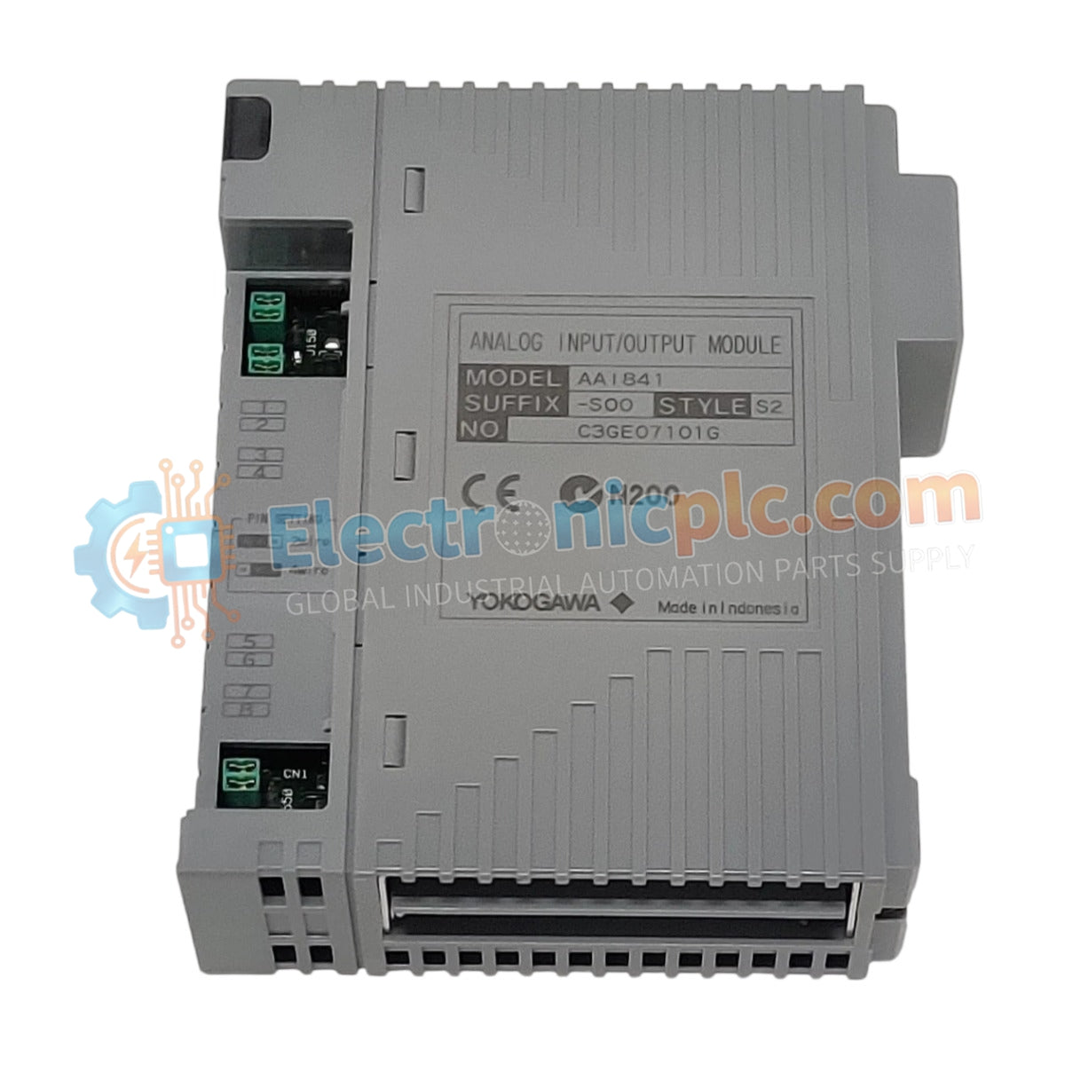

Configured for high-speed pulse acquisition in distributed control system (DCS) platforms, the YOKOGAWA AAP135-S50 (AAP135 Pulse Input Module) provides direct physical pulse counting and frequency measurement execution.
| Parameter | Specification |
|---|---|
| Model | AAP135-S50 |
| Brand | YOKOGAWA |
| Origin | JAPAN |
| Weight | 0.12 kg |
| Dimensions | 10.2 x 8 x 5 cm |
| Operating Temp | -20 to 70 deg C |
| Power Consumption | 1.5 W |
| Signal Input | Pulse Train/Contact Closure |
| Frequency Range | 0.1 Hz to 10 kHz |
| Isolation | Galvanic Channel-to-Channel |
The AAP135-S50 incorporates advanced signal processing to manage pulse input integrity within the DCS environment. The module features channel-to-channel isolation, preventing electrical interference between disparate field sensors from propagating through the backplane. Each input channel supports high-resolution counting logic, essential for flow metering and rotational speed detection. The architecture facilitates direct 4-20 mA loop monitoring compatibility, ensuring that pulse data is synchronized with existing process control loops without external signal conditioning.
Q: Does the AAP135-S50 module support hot-swapping during system operation?
A: Yes, this module supports hot-swapping within a powered chassis, provided the relevant DCS configuration software is set to maintenance mode to prevent unexpected output responses.
Q: Is external power required for the field sensor supply?
A: The module provides an internal excitation voltage for passive contact closures; however, active sensors require an external 24 VDC power source compliant with system grounding requirements.


