My Cart
0 items
Genuine Automation Parts | Worldwide Express Delivery | 12-Month Warranty — [GET A QUOTE]

The YOKOGAWA AAV144-S50/A4S10, also cataloged as the AAV144 Voltage Input Module, operates as a dedicated hardware component for high-precision analog signal acquisition within process control network systems.
Availability: In stock
Reliable Worldwide Delivery
30-Day Money-Back Guarantee
Need more details? Read our fullShipping PolicyandRefund Policy.


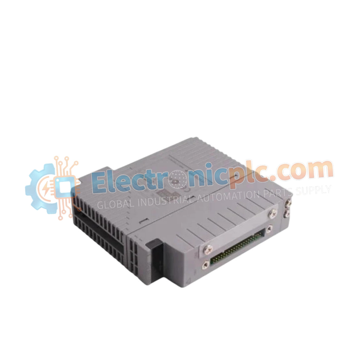
The YOKOGAWA AAV144-S50/A4S10, also cataloged as the AAV144 Voltage Input Module, operates as a dedicated hardware component for high-precision analog signal acquisition within process control network systems.
The AAV144-S50/A4S10 follows a structured ordering format where the suffix denotes specific calibration and safety compliance configurations. The -S50 identifier specifies the hardware versioning for standard input scaling, while the /A4S10 extension signifies the certified range compatibility for 1-5 V and -10 to 10 V input signals.
| Parameter | Specification |
|---|---|
| Model | AAV144-S50/A4S10 |
| Brand | YOKOGAWA |
| Origin | Japan |
| Weight | 0.2 kg |
| Dimensions | 130 mm x 107.5 mm x 32.8 mm |
| Operating Temp | 0 deg C to 50 deg C |
| Power Consumption | 5 VDC nominal |
| Input Channels | 16 (isolated) |
| Input Range | 1-5 V or -10 to 10 V |
| Allowable Input Voltage | +/- 30 V |
| Isolated Voltage | 1500 V AC (1 minute) |
| Accuracy (1-5 V) | +/- 4 mV |
| Accuracy (-10 to 10 V) | +/- 20 mV |
| Data Update Period | 10 ms |
The AAV144-S50/A4S10 utilizes advanced galvanic isolation techniques to ensure high signal fidelity across its 16 input channels. In DCS environments, maintaining channel-to-channel isolation is required to eliminate ground loops and common-mode interference when interfacing with diverse field instruments. While the primary function is voltage input, the architecture is compatible with 4-20 mA HART loop protocol conversion via external shunt resistors, allowing for standardized data integration into the Yokogawa control platform.
Q: Can the input range be configured differently for individual channels?
A: No. The AAV144-S50/A4S10 requires input signals to be configured globally for the entire module (CH1 to CH16). Individual channel range switching is not supported by this hardware version.
Q: What occurs if the input voltage exceeds the +/- 30 V limit?
A: The module is designed to withstand up to +/- 30 V. Exceeding this threshold may result in permanent damage to the input protection circuitry and compromise the isolation barrier.


