My Cart
0 items
Genuine Automation Parts | Worldwide Express Delivery | 12-Month Warranty — [GET A QUOTE]

Configured for high-density signal distribution in distributed control system (DCS) platforms, the YOKOGAWA AAV544-S50 (AAV544 Analog Output Module) provides direct physical voltage execution.
The AAV544-S50...
Availability: Low stock: 99 left
Reliable Worldwide Delivery
30-Day Money-Back Guarantee
Need more details? Read our fullShipping PolicyandRefund Policy.
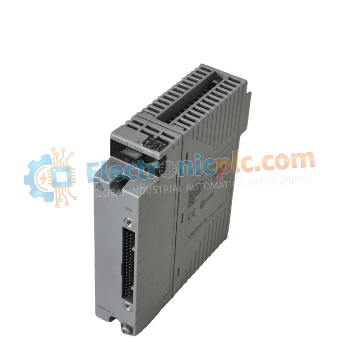

Configured for high-density signal distribution in distributed control system (DCS) platforms, the YOKOGAWA AAV544-S50 (AAV544 Analog Output Module) provides direct physical voltage execution.
The AAV544-S50 denotes a standard-configuration analog output unit designed for high-availability control architectures. The "-S50" suffix signifies the specific hardware revision compatible with standard Yokogawa rack-mount backplanes and supports full dual-redundant deployment within the host system.
| Parameter | Specification |
|---|---|
| Model | AAV544-S50 |
| Brand | YOKOGAWA |
| Origin | japan |
| Weight | 0.2 kg |
| Dimensions | N/A |
| Operating Temp | -20 to 70 deg C |
| Power Consumption | N/A |
| Channels | 16 isolated |
| Voltage Range | -10 VDC to +10 VDC |
| Isolation Voltage | 1500 VAC |
| Update Period | 10 ms |
| Step Response | 40 ms |
The YOKOGAWA AAV544-S50 utilizes advanced channel-to-channel isolation to eliminate ground loop potential in complex process environments. Integrated HART protocol support enables bi-directional digital communication over the analog signal path, facilitating remote device diagnostics and parameterization without requiring additional wiring. The module supports seamless dual-redundant configuration, allowing for continuous signal integrity during primary controller switchover or single-module fault conditions.
Q: Does the AAV544-S50 maintain signal output during a primary module fault in a redundant pair?
A: Yes, in a dual-redundant configuration, the standby module assumes signal output control with a transition latency managed by the backplane bus, ensuring minimal disturbance to the controlled final control elements.
Q: Are the 16 output channels independently galvanically isolated?
A: The module architecture provides channel-to-channel galvanic isolation rated at 1500 VAC, which prevents cross-talk and electrical stress propagation across the output field wiring.


