My Cart
0 items
Genuine Automation Parts | Worldwide Express Delivery | 12-Month Warranty — [GET A QUOTE]

Configured for discrete signal distribution in distributed control system (DCS) platforms, the YOKOGAWA ADR541-P50 (ADR541 Relay Output Module) provides direct physical contact-based execution for actuator control.
Availability: In stock
Reliable Worldwide Delivery
30-Day Money-Back Guarantee
Need more details? Read our fullShipping PolicyandRefund Policy.
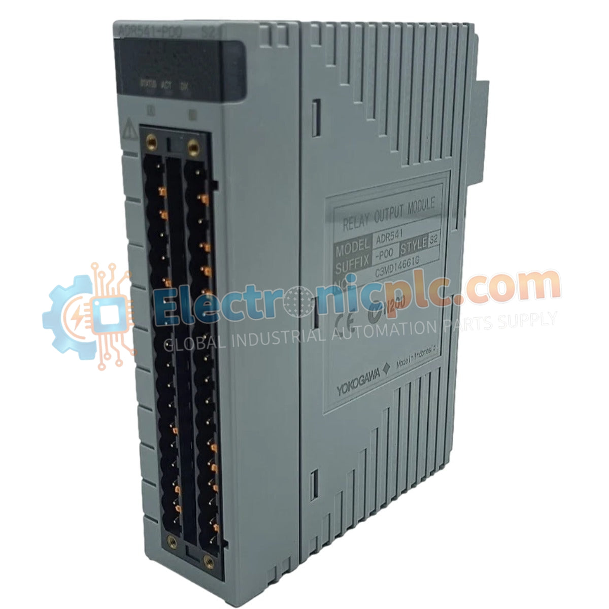
Configured for discrete signal distribution in distributed control system (DCS) platforms, the YOKOGAWA ADR541-P50 (ADR541 Relay Output Module) provides direct physical contact-based execution for actuator control.
The ADR541-P50 utilizes a specific suffix logic to define hardware functionality. The ADR541 series core denotes a 16-channel relay output card. The P suffix designates the inclusion of a Pulse Width Modulation (PWM) time-proportional output function. The 5 indicates a standard model variant, while the terminal 0 represents the basic chassis-compatible design. Alternative variants include the 3 for wide-temperature/corrosion-resistant applications and the E for explosion-proof certification requirements.
| Parameter | Specification |
|---|---|
| Model | ADR541-P50 |
| Brand | YOKOGAWA |
| Origin | JAPAN |
| Weight | 1.0 kg |
| Dimensions | N/A |
| Operating Temp | 0 to 55 deg C |
| Power Consumption | N/A |
| Channels | 16 independent relay |
| Load Voltage | 24-110 VDC / 100-240 VAC |
| Functionality | PWM time-proportional output |
The YOKOGAWA ADR541-P50 integrates 16 independent relay contact channels to manage discrete field device states. The inclusion of PWM time-proportional output functionality allows the module to control actuators requiring variable duty-cycle modulation, providing precise state-based regulation without requiring dedicated analog control loops. Each relay contact is rated for a broad load voltage range, accommodating both DC and AC field circuit requirements, thereby ensuring compatibility with diverse electrical instrumentation and power-handling infrastructure.
Q: Can the ADR541-P50 switch inductive loads directly?
A: While the relay contacts are rated for 24-110 VDC or 100-240 VAC, switching highly inductive loads such as large solenoids or motors requires external suppression (e.g., flyback diodes or RC snubbers) to prevent contact arcing and extend relay service life.
Q: How does the PWM function operate on the relay outputs?
A: The PWM functionality modulates the ON/OFF time-proportional duty cycle of the relay contacts based on signals from the Field Control Station (FCS), allowing the module to actuate devices at average output levels proportional to the control command.


