Skip to product information
1 of 3

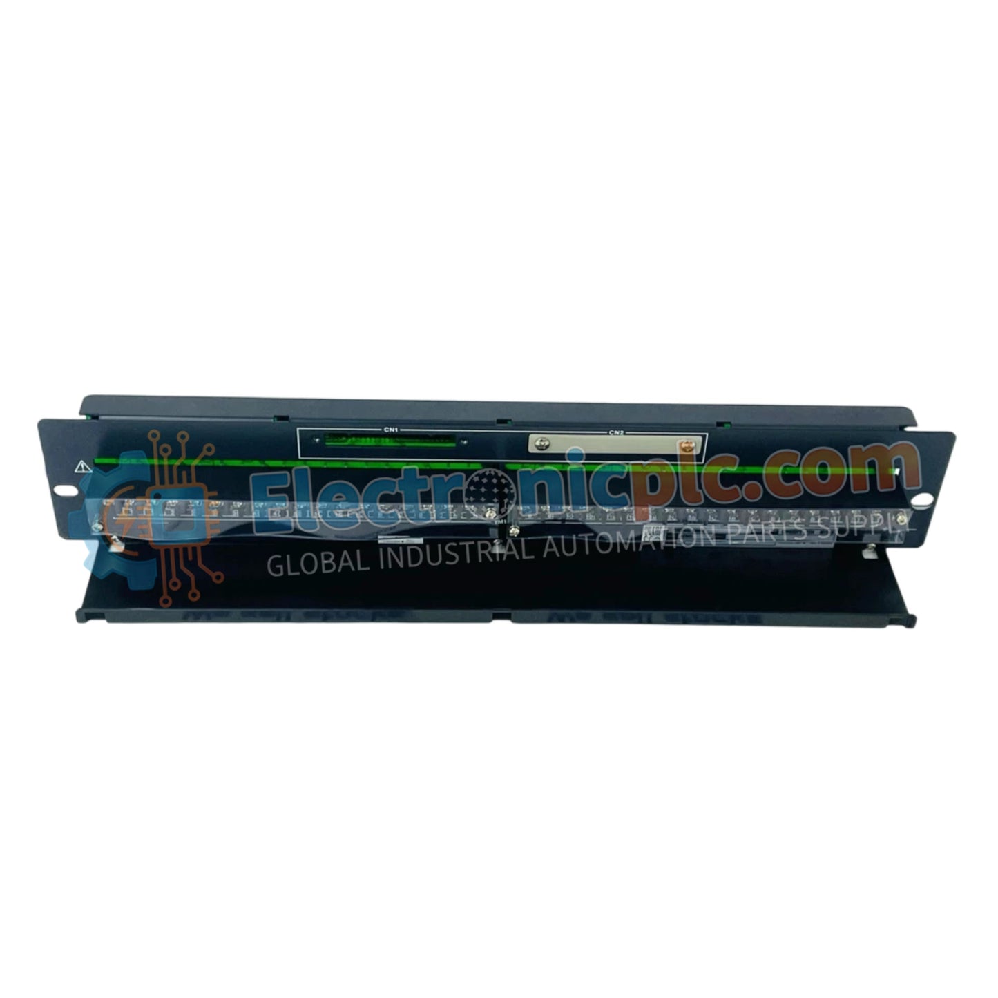
Yokogawa AER4D-05 Node Interface Module

Yokogawa AER4D-05 Node Interface Module

The Yokogawa AER4D-05, also cataloged as the AER4D-05 Node Interface Module, operates as a dedicated hardware component for field signal distribution within Yokogawa industrial control platforms.

Hardware Specifications

...
19 people are viewing this right now

AvailabilityIn stock

SKU: AER4D-05
Vendor: Yokogawa
Related Series:

Shipping & Returns

Reliable Worldwide Delivery

  • Carriers: Shipped via DHL, FedEx, UPS, or USPS.
  • Dispatch: Orders processed in 1-2 business days and dispatched within 3-5 business days.
  • Tracking: Full tracking details provided via email upon shipment.

30-Day Money-Back Guarantee

  • Guarantee: 30-day return window for in-stock, factory-sealed products.
  • Condition: Items must be unopened, unused, and in original packaging.
  • Authenticity: We guarantee 100% original and authentic hardware.

Need more details? Read our fullShipping PolicyandRefund Policy.

Authenticity & Warranty

  • Genuine Guarantee: We supply only 100% original, brand-new, and factory-sealed industrial automation parts.
  • Full Coverage: Every component is backed by a 12-month comprehensive warranty from the date of purchase.
  • Traceability: All products come with original factory documentation and accessories for full industrial compliance.

Technical Support & Sourcing

  • Expert Assistance: Our technical team provides free consultation to help you verify compatibility for DCS and PLC systems.
  • Rare Part Sourcing: Specializing in obsolete and hard-to-find components from Allen-Bradley, Siemens, ABB, HIMA, and more.
  • Bulk Inquiries: Contact us at pambo@5gplc.com for volume pricing or customized project quotes.
View full product details

The Yokogawa AER4D-05, also cataloged as the AER4D-05 Node Interface Module, operates as a dedicated hardware component for field signal distribution within Yokogawa industrial control platforms.

Hardware Specifications

Parameter Specification
Model AER4D-05
Brand Yokogawa
Origin Japan
Weight 1.5 kg
Dimensions 482.6 mm x 88.1 mm x 53 mm
Operating Temp -40 deg C to 85 deg C
Power Consumption Not Specified
Terminal Points 16 points for M4 screws
Insulation Resistance 100 MOhm or greater at 500 VDC
Withstanding Voltage 500 VAC for 1 minute
Enclosure Rating IP65

Process Control and Signal Integrity

The AER4D-05 module is engineered to manage signal routing with high environmental resilience, featuring an IP65-rated enclosure suitable for demanding industrial conditions. The internal circuitry utilizes UL 94 V-0 flame-retardant materials to maintain safety standards under thermal stress. The module provides a robust interface for 16-point connectivity, ensuring low-latency signal transmission while maintaining an insulation resistance of 100 MOhm. This construction supports deterministic performance in distributed control architectures, facilitating reliable process data transit between field devices and central controllers.

Frequently Asked Questions

Q: Is the AER4D-05 module capable of hot-swapping during normal system operation?

A: No. The AER4D-05 does not support hot-swapping. Ensure the system node is powered down and the communication bus is inactive before installation or removal of the module to prevent electrical faults.

Q: What is the specified torque requirement for the M4 terminal screws?

A: The recommended torque for the M4 screws is 0.5 to 0.6 Nm; exceeding this range may cause damage to the terminal block, while under-torquing may lead to high-resistance connections or signal instability.

Field Installation Guidelines

  1. Mount the module securely in a standard 19-inch rack enclosure using the designated mounting points, ensuring the unit is level to prevent mechanical stress on the backplane interface.
  2. Verify that all field wiring is routed to the 16 M4 screw terminals, utilizing appropriate wire lugs to ensure a stable, low-resistance electrical connection.
  3. Confirm that the operating environment is within the -40 deg C to 85 deg C range and that the module is adequately protected from prolonged direct UV exposure or chemical solvents that could compromise the IP65 seal.
  4. Ensure all shielding for incoming signal cables is correctly bonded to the system's earth bus at the cabinet entry to maintain the integrity of the insulation resistance.
  5. Perform a post-installation visual inspection to confirm that all terminal screws are tightened to the specified 0.5 to 0.6 Nm range and that no conductive debris is present near the terminal blocks.