My Cart
0 items
Genuine Automation Parts | Worldwide Express Delivery | 12-Month Warranty — [GET A QUOTE]

Configured for field control station communication within industrial automation networks, the Yokogawa AIP 521 (AIP 521 Control Bus Coupler) provides direct physical and electrical interface execution for system bus traffic.
...Availability: In stock
Reliable Worldwide Delivery
30-Day Money-Back Guarantee
Need more details? Read our fullShipping PolicyandRefund Policy.


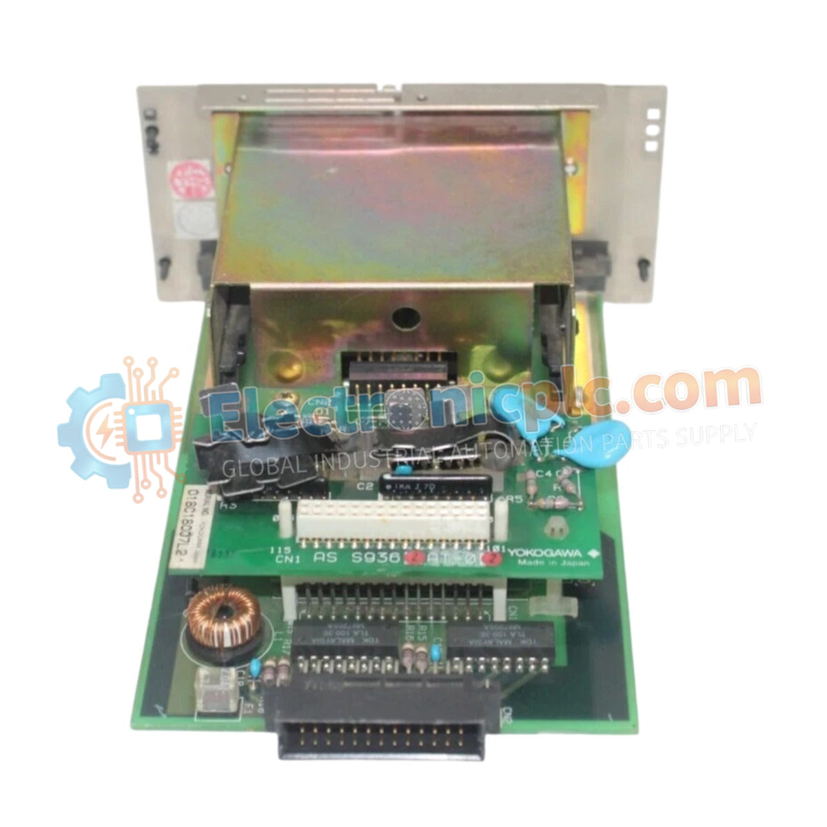
Configured for field control station communication within industrial automation networks, the Yokogawa AIP 521 (AIP 521 Control Bus Coupler) provides direct physical and electrical interface execution for system bus traffic.
| Parameter | Specification |
|---|---|
| Model | AIP 521 |
| Brand | Yokogawa |
| Origin | Japan |
| Weight | 0.48 kg |
| Dimensions | 15.2 cm x 5.1 cm x 22.9 cm |
| Operating Temp | Standard industrial range |
| Power Consumption | Integrated CPU backup supply |
| Communication Protocols | HART, Foundation Fieldbus, Profibus |
| Form Factor | Modular plug-in design |
The AIP 521 facilitates seamless data transmission across process control architectures by supporting multi-protocol environments. The hardware architecture incorporates specialized circuitry to manage 4-20 mA HART loop protocol integration, ensuring accurate digital data overlay on analog signals. Furthermore, the module enables robust connectivity for Foundation Fieldbus and Profibus PA segments, maintaining signal integrity through channel-to-channel isolation. The onboard CPU backup power supply architecture ensures that critical field control parameters are maintained during primary power transients, mitigating the risk of volatile memory loss or communication mastership drops.
Q: Does the AIP 521 support hot-swapping during active system operation?
A: No. The hardware design requires the removal of power from the relevant backplane segment before extraction to prevent potential electrical arcing or data bus corruption.
Q: How does the module handle power failure scenarios?
A: The AIP 521 utilizes an integrated CPU backup power supply system designed to sustain internal logic and communication state memory for a predetermined interval during primary input power loss, allowing for controlled system shutdown or transition to secondary controllers.


