Skip to product information
1 of 3

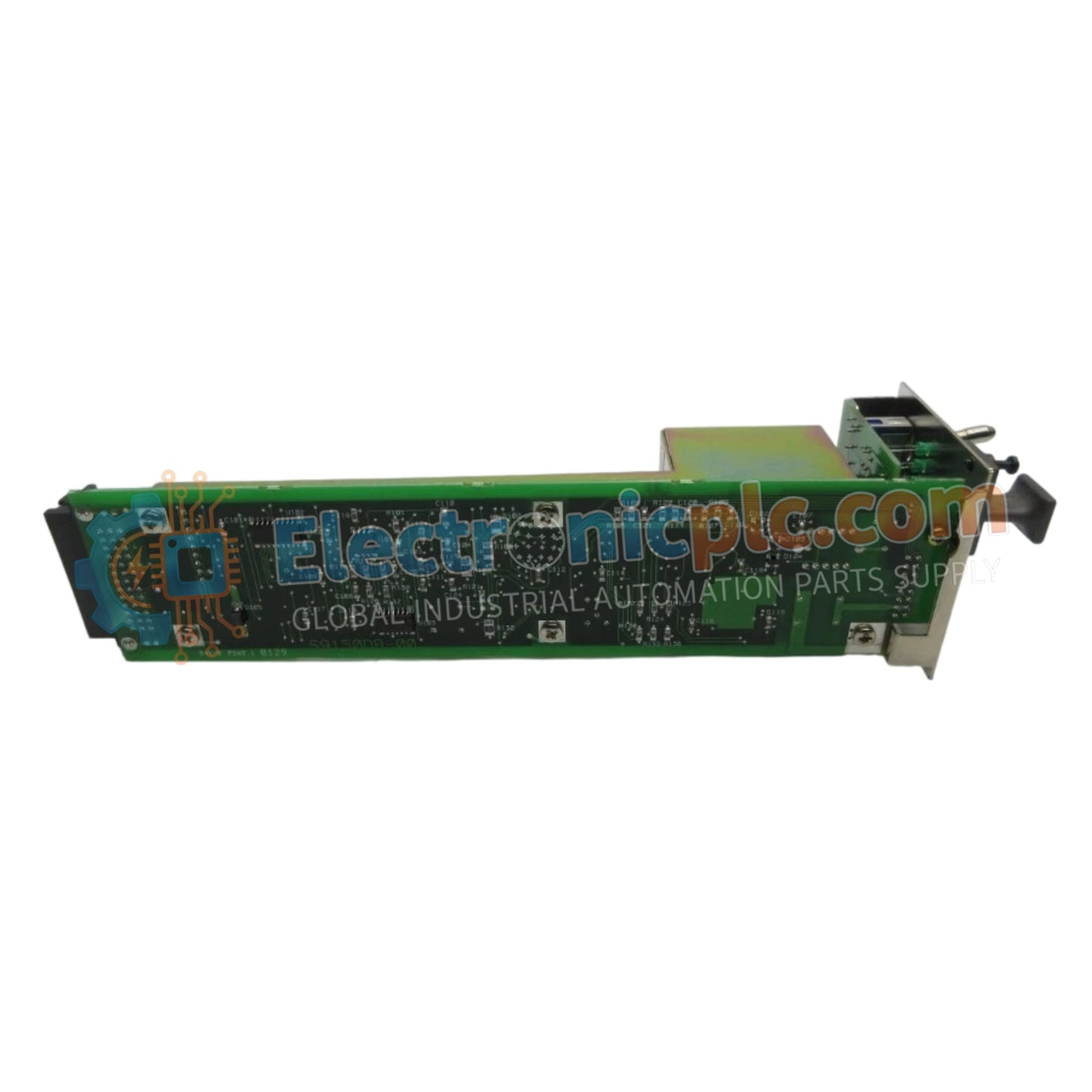
Yokogawa AIP512S2 Remote I/O Bus Connection Module

Yokogawa AIP512S2 Remote I/O Bus Connection Module

Configured for scalable integration within CENTUM industrial control networks, the Yokogawa AIP512 S2 (AIP512 Remote I/O Bus Connection Module) provides direct physical/electrical execution of ESB bus communication between control stations...

24 people are viewing this right now

AvailabilityIn stock

SKU: AIP512S2
Vendor: Yokogawa

Shipping & Returns

Reliable Worldwide Delivery

  • Carriers: Shipped via DHL, FedEx, UPS, or USPS.
  • Dispatch: Orders processed in 1-2 business days and dispatched within 3-5 business days.
  • Tracking: Full tracking details provided via email upon shipment.

30-Day Money-Back Guarantee

  • Guarantee: 30-day return window for in-stock, factory-sealed products.
  • Condition: Items must be unopened, unused, and in original packaging.
  • Authenticity: We guarantee 100% original and authentic hardware.

Need more details? Read our fullShipping PolicyandRefund Policy.

Authenticity & Warranty

  • Genuine Guarantee: We supply only 100% original, brand-new, and factory-sealed industrial automation parts.
  • Full Coverage: Every component is backed by a 12-month comprehensive warranty from the date of purchase.
  • Traceability: All products come with original factory documentation and accessories for full industrial compliance.

Technical Support & Sourcing

  • Expert Assistance: Our technical team provides free consultation to help you verify compatibility for DCS and PLC systems.
  • Rare Part Sourcing: Specializing in obsolete and hard-to-find components from Allen-Bradley, Siemens, ABB, HIMA, and more.
  • Bulk Inquiries: Contact us at pambo@5gplc.com for volume pricing or customized project quotes.
View full product details

Configured for scalable integration within CENTUM industrial control networks, the Yokogawa AIP512 S2 (AIP512 Remote I/O Bus Connection Module) provides direct physical/electrical execution of ESB bus communication between control stations and distributed remote I/O devices.

Suffix Breakdown & Model Matrix

  • AIP512: Base module designation for an ESB bus-compatible remote I/O interface.
  • S2: Suffix indicating the specific hardware revision for optimized signal transmission and connector compatibility.

Hardware Specifications

Parameter Specification
Model AIP512 S2
Brand Yokogawa
Origin japan
Weight 0.20 kg (0.45 lbs)
Dimensions 225 mm x 140 mm x 92 mm
Operating Temp -20 deg C to 55 deg C
Power Consumption 15 W
Current Consumption 0.5 A
Protocol ESB Bus
Transmission Speed 128 Mbps
Max Distance 10 meters

Industrial Control and Network Connectivity

The AIP512 S2 acts as the critical bridge for Remote I/O (RIO) data traffic, facilitating deterministic communication at speeds of up to 128 Mbps across the ESB bus architecture. Designed for high-speed synchronization, this module ensures that field-level signal data is transmitted to the control station with minimal latency. The interface utilizes twisted-pair cabling with secure M4 screw terminals to mitigate electromagnetic interference, providing a robust physical layer for reliable signal distribution in process automation environments.

Frequently Asked Questions

Q: Does the AIP512 S2 support hot-swapping during active system operation?

A: No. The AIP512 S2 does not support hot-swapping. Ensure that the associated control node is fully powered down and the ESB bus is inactive before initiating any maintenance or replacement of the module.

Q: Is the 10-meter maximum transmission distance strictly enforced?

A: Yes. The 128 Mbps transmission speed is optimized for the specified maximum distance of 10 meters. Exceeding this length may introduce signal attenuation or timing jitter, which can lead to data transmission errors or loss of communication with remote devices.

Field Installation Guidelines

  1. Mount the module in a well-ventilated enclosure to maintain the operating temperature between -20 deg C and 55 deg C, ensuring adequate clearance for cabling.
  2. Utilize high-quality twisted-pair cabling for the ESB bus connection, ensuring that all conductors are firmly secured to the M4 screw terminals.
  3. Observe the 10-meter limit between nodes; keep the cabling routed away from high-power equipment or frequency-drive cabling to avoid inductive noise.
  4. Ensure all shield drain wires are properly grounded at the designated chassis ground point to maintain the integrity of the high-speed data signals.
  5. Verify that the module is correctly seated and diagnostic indicators are within the normal operating range via the engineering station before enabling remote I/O communication.