Skip to product information
1 of 3

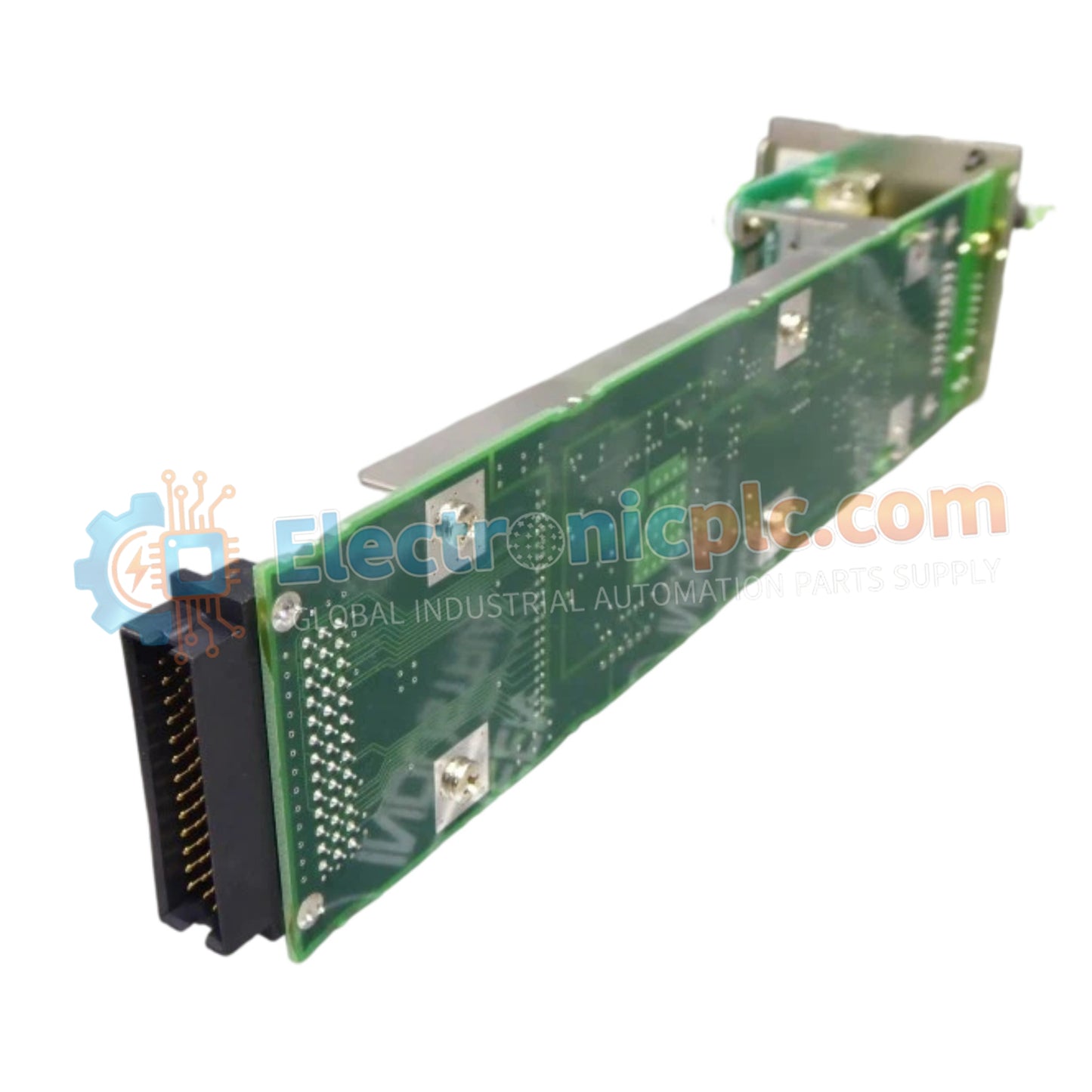
YOKOGAWA AIP532/S1 ESB Bus Coupler Module

YOKOGAWA AIP532/S1 ESB Bus Coupler Module

Configured for high-speed data transmission in distributed control architectures, the YOKOGAWA AIP532/S1 (AIP532 ESB Bus Coupler Module) provides direct physical/electrical execution. This hardware component serves as the primary ESB (Enterprise...

27 people are viewing this right now

AvailabilityIn stock

SKU: AIP532/S1
Vendor: Yokogawa
Related Series:

Shipping & Returns

Reliable Worldwide Delivery

  • Carriers: Shipped via DHL, FedEx, UPS, or USPS.
  • Dispatch: Orders processed in 1-2 business days and dispatched within 3-5 business days.
  • Tracking: Full tracking details provided via email upon shipment.

30-Day Money-Back Guarantee

  • Guarantee: 30-day return window for in-stock, factory-sealed products.
  • Condition: Items must be unopened, unused, and in original packaging.
  • Authenticity: We guarantee 100% original and authentic hardware.

Need more details? Read our fullShipping PolicyandRefund Policy.

Authenticity & Warranty

  • Genuine Guarantee: We supply only 100% original, brand-new, and factory-sealed industrial automation parts.
  • Full Coverage: Every component is backed by a 12-month comprehensive warranty from the date of purchase.
  • Traceability: All products come with original factory documentation and accessories for full industrial compliance.

Technical Support & Sourcing

  • Expert Assistance: Our technical team provides free consultation to help you verify compatibility for DCS and PLC systems.
  • Rare Part Sourcing: Specializing in obsolete and hard-to-find components from Allen-Bradley, Siemens, ABB, HIMA, and more.
  • Bulk Inquiries: Contact us at pambo@5gplc.com for volume pricing or customized project quotes.
View full product details

Configured for high-speed data transmission in distributed control architectures, the YOKOGAWA AIP532/S1 (AIP532 ESB Bus Coupler Module) provides direct physical/electrical execution. This hardware component serves as the primary ESB (Enterprise System Bus) coupler utilized to execute secure, deterministic communication between Yokogawa field control stations (FCS) and remote I/O node units across industrial control platforms.

Suffix Breakdown & Model Matrix

  • AIP532: Base model identifier for the ESB Bus Coupler Module.
  • /S1: Manufacturing revision or hardware configuration identifier.

Hardware Specifications

Parameter Specification
Model AIP532/S1
Brand YOKOGAWA
Origin JAPAN
Weight 0.2 kg
Dimensions 6.3 cm x 6.3 cm x 24.1 cm
Power Consumption ≤ 5 W (Typical)
Communication Interface ESB Bus
Bus Topology Point-to-Point / Serial Bus

Industrial Communication and System Integration

The AIP532/S1 acts as the interface bridge within Yokogawa CENTUM control systems, ensuring robust data throughput between the Field Control Unit (FCU) and connected I/O nodes. It manages electrical signal conversion and packet integrity on the ESB bus, supporting the synchronization requirements of distributed process control. By facilitating seamless expansion of I/O capacity, the module enables deterministic scan cycles essential for safety and efficiency in complex industrial automation environments.

Frequently Asked Questions

Q: Is the AIP532/S1 compatible with legacy FIO (Fieldbus I/O) node units?

A: The AIP532 is designed specifically for ESB bus communication interfaces; verify the compatibility of your specific base plate and node unit revision in the Yokogawa General Specifications (GS) documentation.

Q: Does this module support redundant bus configurations?

A: Yes, in dual-redundant ESB bus architectures, the AIP532 modules must be installed in designated pairs (odd/even slot configurations) to ensure continuous operation in the event of a single module fault.

Field Installation Guidelines

  • Ensure the node unit backplane is de-energized before inserting or removing the AIP532 module to prevent electrical damage to the communication pins.
  • Align the module with the card guides on the node unit base plate and ensure the locking mechanism is fully engaged for a secure backplane connection.
  • Verify that ESB bus terminators are installed correctly at the end of the bus segment to prevent signal reflections and data errors.
  • Route ESB bus cables through dedicated cable trays to isolate them from high-voltage power lines and reduce electromagnetic interference.
  • Check the status LEDs on the module front panel after installation to confirm established link health and active communication status with the control station.