My Cart
0 items
Genuine Automation Parts | Worldwide Express Delivery | 12-Month Warranty — [GET A QUOTE]

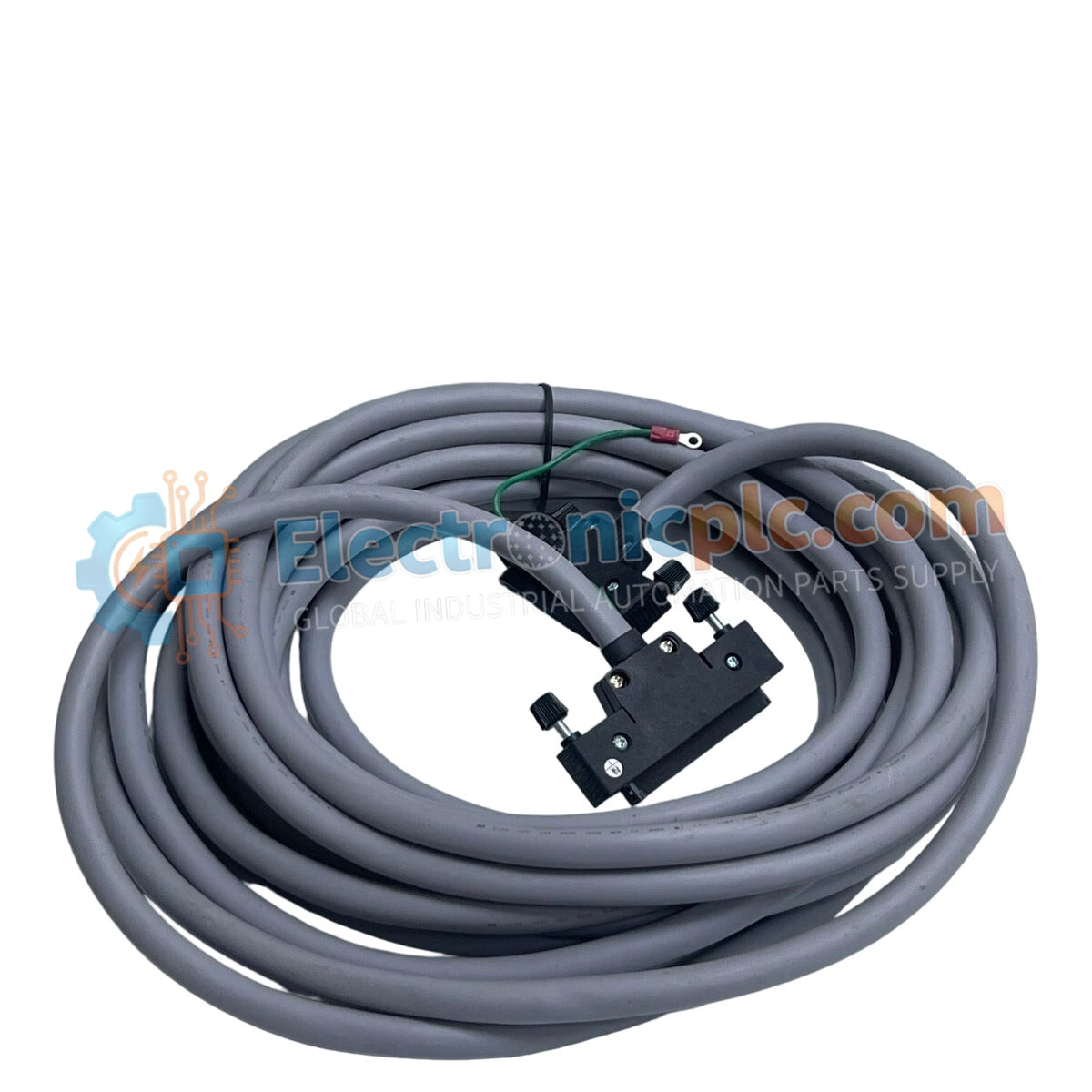
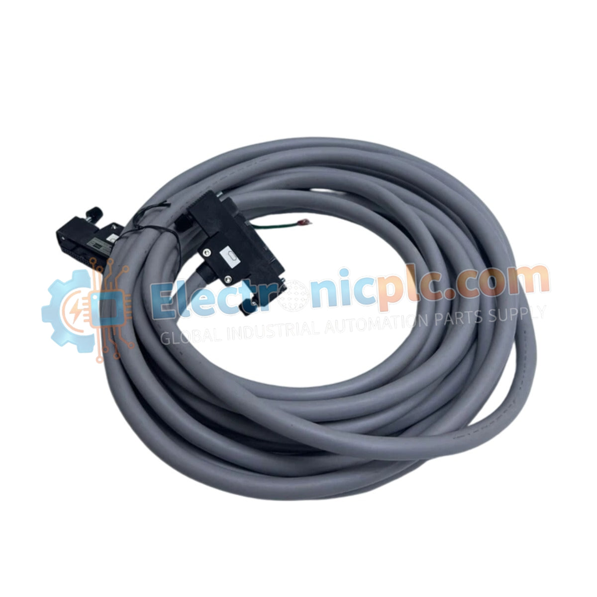
Configured for serial data transmission between control interfaces, the YOKOGAWA AKB161-M100 (AKB161 Signal Cable) provides direct physical/electrical execution of RS-422 and RS-485 communication protocols between M4 and M3 terminal assemblies.
...Availability: Low stock: 99 left
Reliable Worldwide Delivery
30-Day Money-Back Guarantee
Need more details? Read our fullShipping PolicyandRefund Policy.

Configured for serial data transmission between control interfaces, the YOKOGAWA AKB161-M100 (AKB161 Signal Cable) provides direct physical/electrical execution of RS-422 and RS-485 communication protocols between M4 and M3 terminal assemblies.
| Parameter | Specification |
|---|---|
| Model | AKB161-M100 |
| Brand | YOKOGAWA |
| Origin | japan |
| Weight | 0.68kg |
| Dimensions | Max length 100 m |
| Operating Temp | Standard Industrial Range |
| Power Consumption | Passive Component |
| Terminal Side A | M4 Terminal |
| Terminal Side B | M3 Terminal |
The AKB161-M100 is engineered to maintain signal integrity for differential serial protocols (RS-422/RS-485) across distributed distances. The cable construction utilizes twisted-pair conductors to provide high common-mode noise rejection, which is necessary for stable data exchange in environments with significant electromagnetic interference. The physical interface architecture ensures that signal attenuation remains within the operational requirements for RS-485 bus protocols over the full 100-meter span, preventing data packet loss or framing errors during asynchronous communication.
Q: Can the AKB161 cable be extended beyond the 100-meter maximum length?
A: Extending the cable beyond 100 meters is not recommended, as signal attenuation and reflections will exceed the tolerances of the RS-422/RS-485 physical layer, likely resulting in communication failure.
Q: Are the M4 and M3 terminals field-interchangeable?
A: The terminals are application-specific; ensure the M4 side is connected to the ALM port and the M3 side to the target field terminal block as specified in the hardware documentation.


