
My Cart
0 items
Genuine Automation Parts | Worldwide Express Delivery | 12-Month Warranty — [GET A QUOTE]

Configured for high-density signal transmission in distributed control system platforms, the Yokogawa AKB331-M015 S3 (AKB331 Signal Cable) provides direct physical electrical interconnection between process I/O modules and terminal blocks.
Availability: In stock
Reliable Worldwide Delivery
30-Day Money-Back Guarantee
Need more details? Read our fullShipping PolicyandRefund Policy.


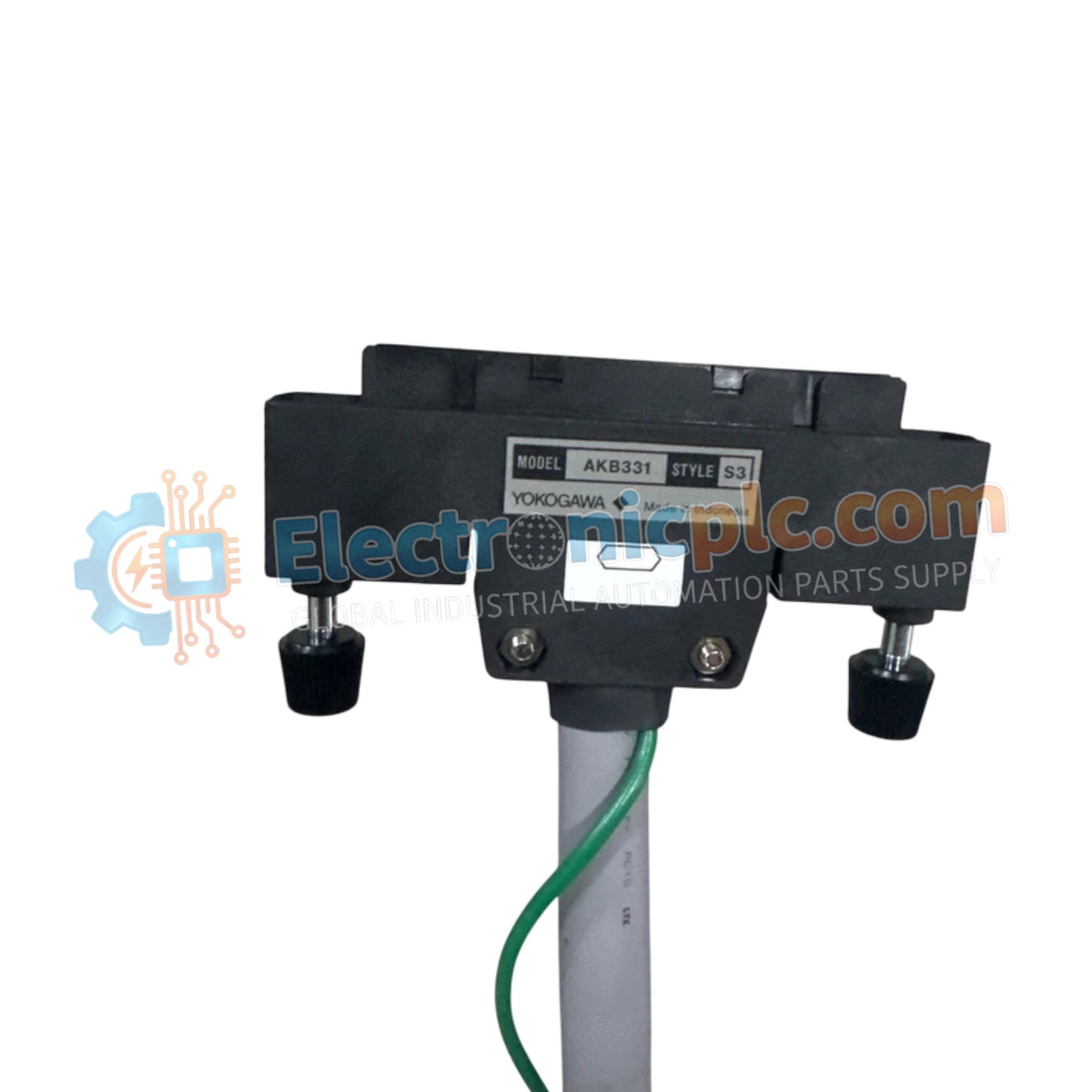
Configured for high-density signal transmission in distributed control system platforms, the Yokogawa AKB331-M015 S3 (AKB331 Signal Cable) provides direct physical electrical interconnection between process I/O modules and terminal blocks.
| Parameter | Specification |
|---|---|
| Model | AKB331-M015 S3 |
| Brand | Yokogawa |
| Origin | Japan |
| Weight | 4 kg |
| Dimensions | 15 m (length) |
| Operating Temp | -20 to 70 deg C (storage/operational) |
| Power Consumption | Not applicable (Passive component) |
| Pin Configuration | 50-pin to 50-pin |
| Insulation Resistance | 50 M ohms minimum at 500 V DC |
The AKB331 series employs multi-conductor shielded construction to maintain 4-20 mA HART loop protocol integrity and digital signal clarity within DCS cabinets. The integration of 50-pin connectors facilitates channel-to-channel signal mapping across high-density I/O arrays. To prevent crosstalk and signal attenuation over the 15 m span, the internal conductors are designed to meet standard impedance requirements for fieldbus communication. Proper grounding of the cable shield at the designated cabinet chassis point is required to mitigate electromagnetic interference in high-noise environments.
Q: Can this cable be trimmed to shorter lengths for specific cabinet applications?
A: It is not recommended to modify the length of the AKB331-M015 S3. Altering the cable impacts the integrity of the factory-molded 50-pin connectors and may compromise the shielded signal path or the mechanical reliability of the connection.
Q: Are there specific requirements for routing this signal cable near AC power lines?
A: Yes. Maintain a minimum separation of 150 mm between the signal cable and any high-voltage AC power conduits to minimize induced noise and crosstalk on low-voltage signal lines.


