My Cart
0 items
Genuine Automation Parts | Worldwide Express Delivery | 12-Month Warranty — [GET A QUOTE]

Configured for high-density signal transmission in DCS architectures, the Yokogawa AKB331-M015 (AKB331 Signal Cable) provides direct physical/electrical execution of data path connectivity between I/O modules and terminal blocks.
Availability: In stock
Reliable Worldwide Delivery
30-Day Money-Back Guarantee
Need more details? Read our fullShipping PolicyandRefund Policy.


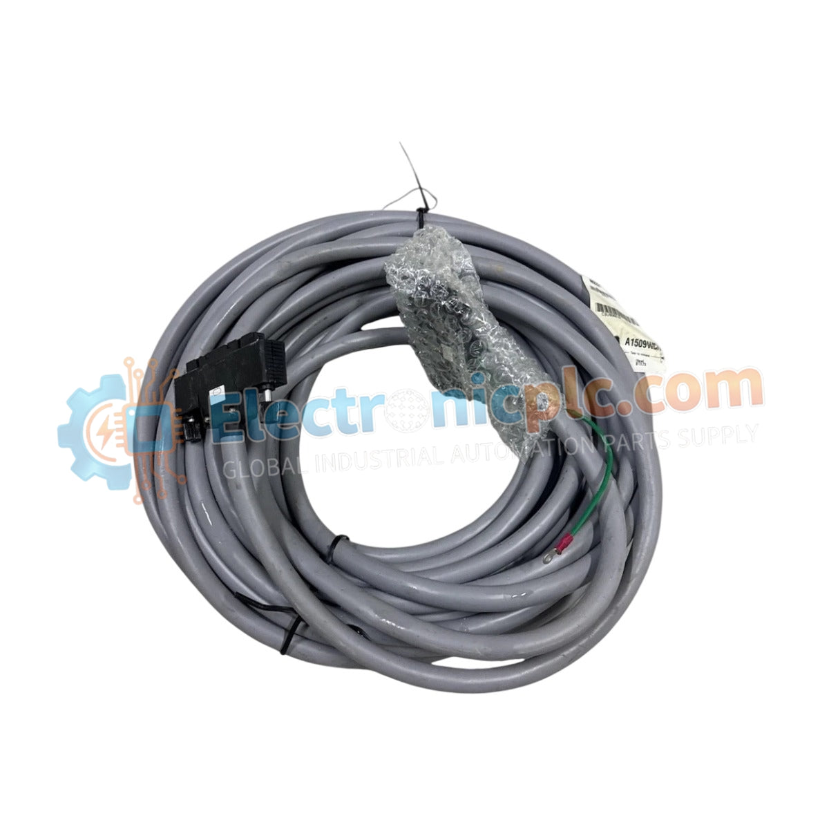
Configured for high-density signal transmission in DCS architectures, the Yokogawa AKB331-M015 (AKB331 Signal Cable) provides direct physical/electrical execution of data path connectivity between I/O modules and terminal blocks.
| Parameter | Specification |
|---|---|
| Model | AKB331-M015 |
| Brand | Yokogawa |
| Origin | Japan |
| Weight | 0.8 kg |
| Dimensions | 1.5 m length |
| Operating Temp | -20 deg C to 70 deg C |
| Power Consumption | Passive cabling assembly |
| Connector Type | System-specific multi-pin |
The AKB331-M015 operates as a dedicated hardware component for bridging field-side termination to internal control systems. The cable assembly is engineered to maintain signal integrity through controlled impedance and shielding, minimizing crosstalk between adjacent lines in high-density I/O configurations. As a passive interconnect, it requires no configuration; however, the shielding is critical to prevent radiated interference from affecting low-level analog signal loops. Users must ensure that the cable is routed away from high-voltage AC paths to prevent induced noise, which could degrade the measurement precision of the connected DCS I/O modules.
Q: Is the AKB331-M015 shielded?
A: Yes. The cable assembly includes internal shielding designed to suppress electromagnetic interference (EMI). To be effective, the shield must be correctly terminated to the system earth ground at the terminal block or cabinet entry point.
Q: Can the cable be field-modified or shortened?
A: Modifying the cable length is not recommended. The electrical characteristics, including impedance and capacitance, are factory-tuned to the system's specifications. Shortening or splicing the cable may introduce signal attenuation or impedance mismatches that affect transmission accuracy.


