My Cart
0 items
Genuine Automation Parts | Worldwide Express Delivery | 12-Month Warranty — [GET A QUOTE]

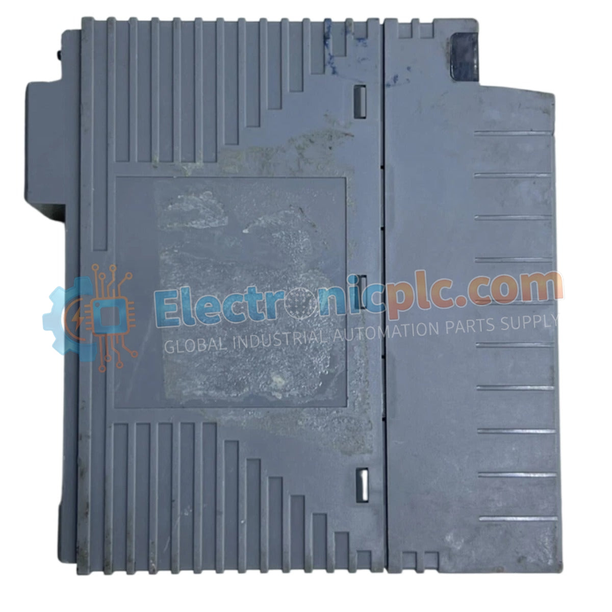
The Yokogawa ALF111-S50 serves as the primary ALF111 FOUNDATION Fieldbus Communication Module utilized to execute deterministic data acquisition and control across DCS network platforms.
| Parameter | Specification |
|---|---|
| Model | ALF111-S50 |
| Brand | Yokogawa |
| Origin | Japan |
| Weight | 0.35 kg |
| Dimensions | 3.2 x 12.4 x 13 cm |
| Operating Temp | Industrial Standard |
| Power Consumption | Not Specified |
| Protocol | FOUNDATION Fieldbus |
The ALF111-S50 module integrates into Yokogawa DCS environments to manage complex FOUNDATION Fieldbus segments. It supports 4-20 mA HART loop protocol translation via gateway bridging, allowing for the coexistence of legacy instrumentation and digital fieldbus devices. The module incorporates robust channel-to-channel isolation to maintain signal integrity and prevent ground loops within high-density control racks. Cold junction compensation (CJC) is managed through system-level backplane monitoring, ensuring consistent accuracy for integrated temperature measurement loops under varying process conditions.
Q: Is this module capable of supporting hot-swap operations?
A: Hot-swapping the module is dependent on the specific system chassis configuration. Verify the I/O bus power state through the DCS maintenance terminal before extraction to ensure communication stability on the active fieldbus segment.
Q: How is the fieldbus power managed by the ALF111-S50?
A: The module does not provide internal fieldbus power; it requires an external FOUNDATION Fieldbus power supply (FF-PS) to be coupled to the segment, ensuring voltage levels remain within the 9 VDC to 32 VDC range for all connected field devices.