
My Cart
0 items
Genuine Automation Parts | Worldwide Express Delivery | 12-Month Warranty — [GET A QUOTE]

Configured for serial communication data processing in CENTUM control networks, the YOKOGAWA ALR121-S53 (ALR121 Circuit Board) provides direct physical signal conversion and protocol handling for field instrumentation.
Availability: In stock
Reliable Worldwide Delivery
30-Day Money-Back Guarantee
Need more details? Read our fullShipping PolicyandRefund Policy.


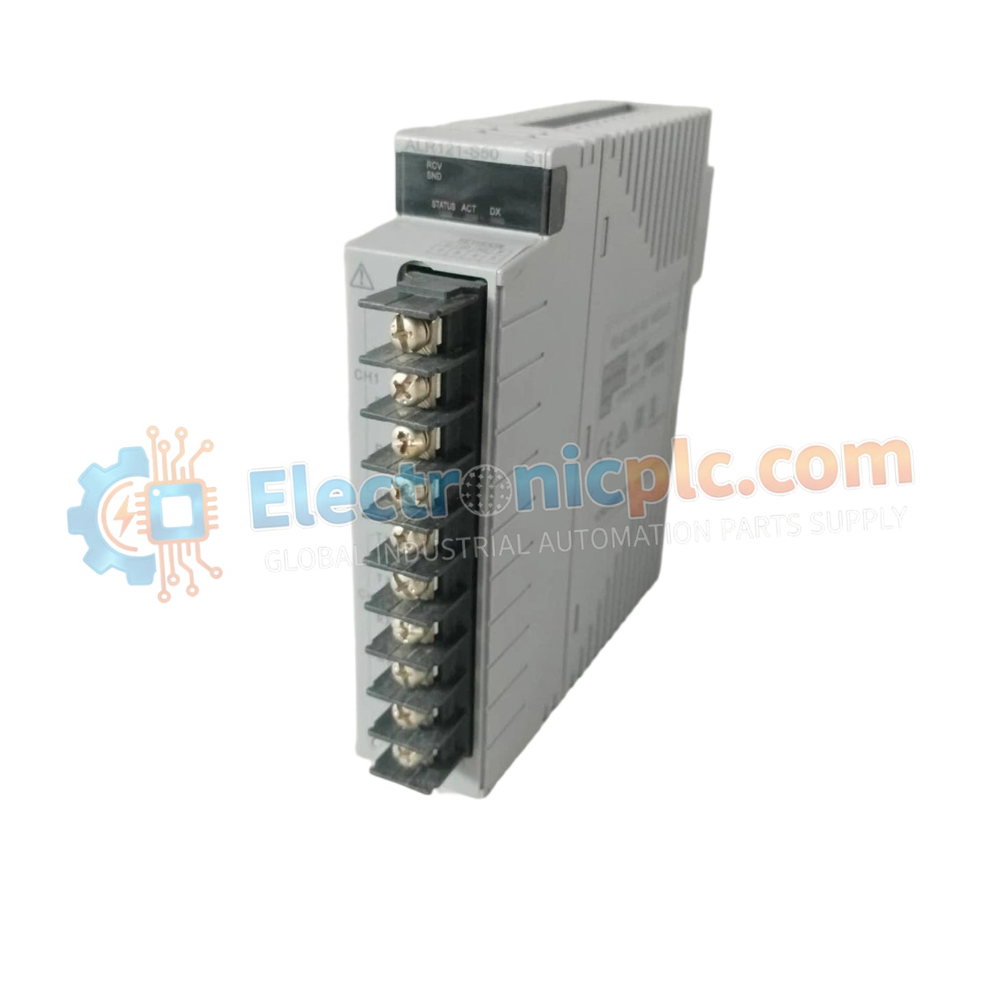
Configured for serial communication data processing in CENTUM control networks, the YOKOGAWA ALR121-S53 (ALR121 Circuit Board) provides direct physical signal conversion and protocol handling for field instrumentation.
| Parameter | Specification |
|---|---|
| Model | ALR121-S53 |
| Brand | YOKOGAWA |
| Origin | Japan |
| Weight | 0.3 kg |
| Dimensions | 7.6 cm x 3 cm x 5.2 cm |
| Operating Temp | 0 deg C to 50 deg C |
| Power Consumption | Not specified |
| Function | Serial Communication / Data Processing |
The ALR121-S53 is engineered to manage high-speed serial data transit while maintaining the signal integrity required for process control environments. The board utilizes advanced filtering stages to support 4-20 mA HART loop protocol connectivity, ensuring that diagnostic data from smart field devices is accurately processed and transmitted to the system controller. By implementing channel-to-channel isolation on the board-level circuitry, the component effectively mitigates the risk of ground loops and common-mode noise, maintaining the high levels of precision required for critical process loops.
Q: Can this circuit board be serviced or repaired at the component level?
A: No, field-level repair of circuit board components (such as soldering surface-mount devices) is not supported. The board is designed as a field-replaceable unit (FRU) and must be replaced in its entirety if diagnostic testing indicates a hardware failure.
Q: How should the board be handled to prevent electrostatic discharge (ESD) damage?
A: Always utilize an ESD-safe workstation, including a wrist strap and grounded mat, when handling the circuit board. Avoid touching the gold-plated edge connectors or high-density integrated circuits to prevent transient voltage damage to the board's internal logic.


