
My Cart
0 items
Genuine Automation Parts | Worldwide Express Delivery | 12-Month Warranty — [GET A QUOTE]

Configured for long-distance signal extension in distributed control networks, the YOKOGAWA ANT401-50/CU1T (ANT401-50 Optical ESB Bus Repeater Master Module) provides direct physical/electrical execution for optical signal conversion. This module facilitates the transmission of...
Availability: In stock
Reliable Worldwide Delivery
30-Day Money-Back Guarantee
Need more details? Read our fullShipping PolicyandRefund Policy.


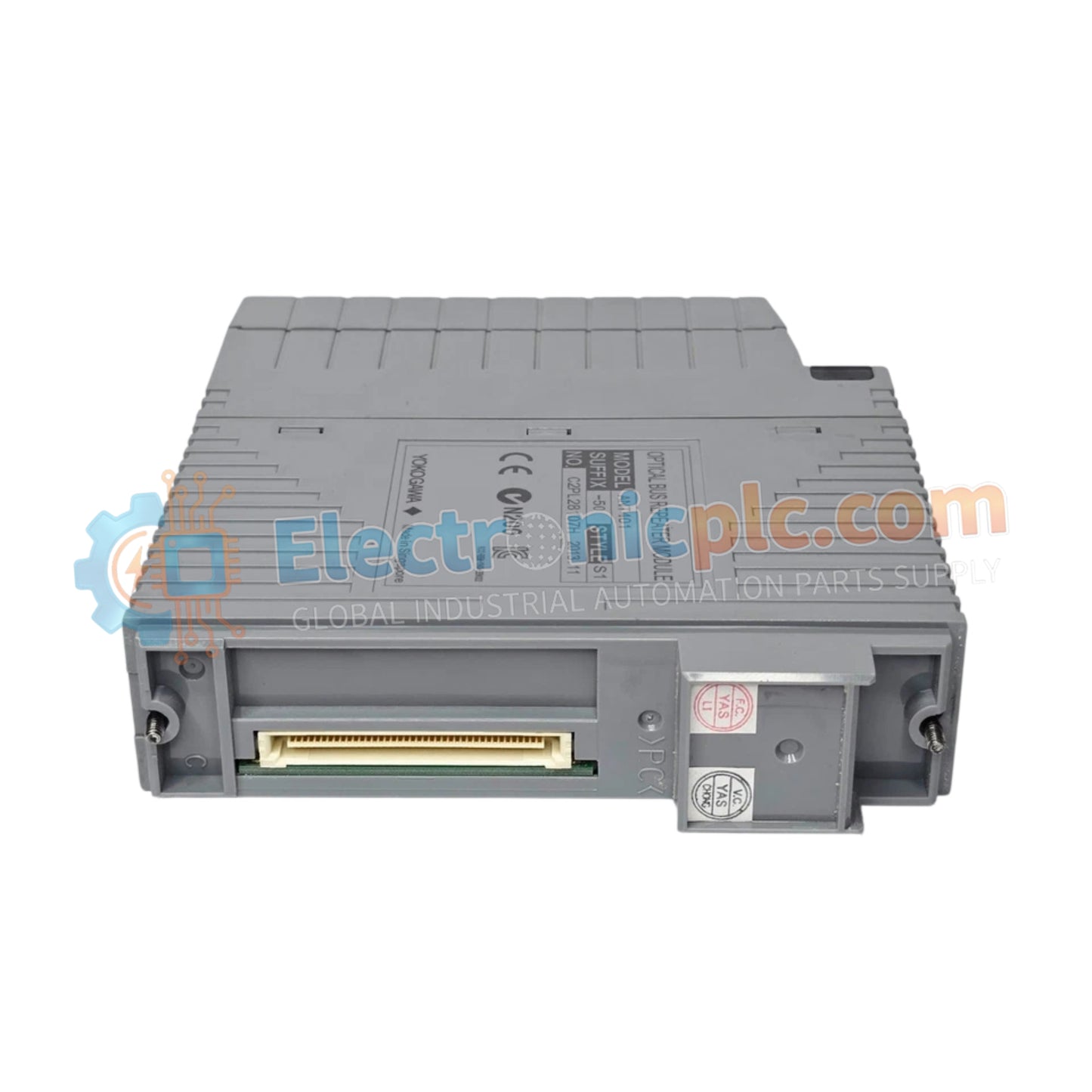
Configured for long-distance signal extension in distributed control networks, the YOKOGAWA ANT401-50/CU1T (ANT401-50 Optical ESB Bus Repeater Master Module) provides direct physical/electrical execution for optical signal conversion. This module facilitates the transmission of ESB bus data across ranges of up to 50 km, serving as the master interface for remote instrumentation clusters.
The ANT401-50/CU1T comprises specific build variants optimized for network topology:
ANT401-50: Specifies the Optical ESB Bus Repeater Master Module base unit.
5: Designates the standard version without integrated explosion protection certification.
0: Specifies the basic functionality set.
/CU1T: Indicates the inclusion of a connector unit equipped with an ESB bus terminator.
| Parameter | Specification |
| Model | ANT401-50/CU1T |
| Brand | YOKOGAWA |
| Origin | JAPAN |
| Weight | 0.25 kg |
| Dimensions | Standard Module Enclosure |
| Operating Temp | Industrial Standard |
| Power Consumption | 0.5 A |
| Transmission Range | 5 km to 50 km |
The ANT401-50 employs internal signal processing to ensure that ESB bus communication remains stable over extended fiber-optic paths. By converting electrical bus signals into optical signals, the module maintains strict timing protocols required for FOUNDATION Fieldbus and similar deterministic communication architectures. This implementation ensures that latency remains within system-specified tolerances, preventing data collisions or frame loss during multi-master operations across geographically dispersed control nodes.
Q: Can the ANT401-50/CU1T be utilized in a dual-redundant configuration?
A: Yes, the module is designed to support both single and dual-redundant configurations. When implemented in a redundant pair, the master module ensures automatic failover to the secondary communication link without disrupting bus traffic.
Q: Is the /CU1T connector unit necessary for the final node in the ESB bus string?
A: Yes, the /CU1T includes a terminator required to match the line impedance at the end of the ESB bus. Failure to properly terminate the bus segment can lead to signal reflections and communication errors.
Ensure that the fiber-optic cable connectors (LC/SC/ST as applicable) are cleaned with approved lint-free wipes and isopropyl alcohol before insertion into the transceiver ports to minimize optical insertion loss.
If installing in a redundant configuration, ensure that both modules are mapped to the correct ESB bus addresses in the controller software before powering the bus segments.
Secure the module into the designated slot on the base plate using the integrated retention screws to guarantee a solid electrical connection to the backplane.
Route optical cables within dedicated conduits to protect the glass fibers from excessive bending radii or mechanical stress.
Verify the terminator switch or connector unit (/CU1T) is correctly applied only at the physical end-of-line position on the bus to maintain signal integrity.


