My Cart
0 items
Genuine Automation Parts | Worldwide Express Delivery | 12-Month Warranty — [GET A QUOTE]

The Yokogawa ANT401-5E, also cataloged as the ANT401-5E Optical ESB Bus Module, operates as a dedicated hardware component for extending ESB bus signal transmission ranges via optical conversion within DCS...
Availability: In stock
Reliable Worldwide Delivery
30-Day Money-Back Guarantee
Need more details? Read our fullShipping PolicyandRefund Policy.
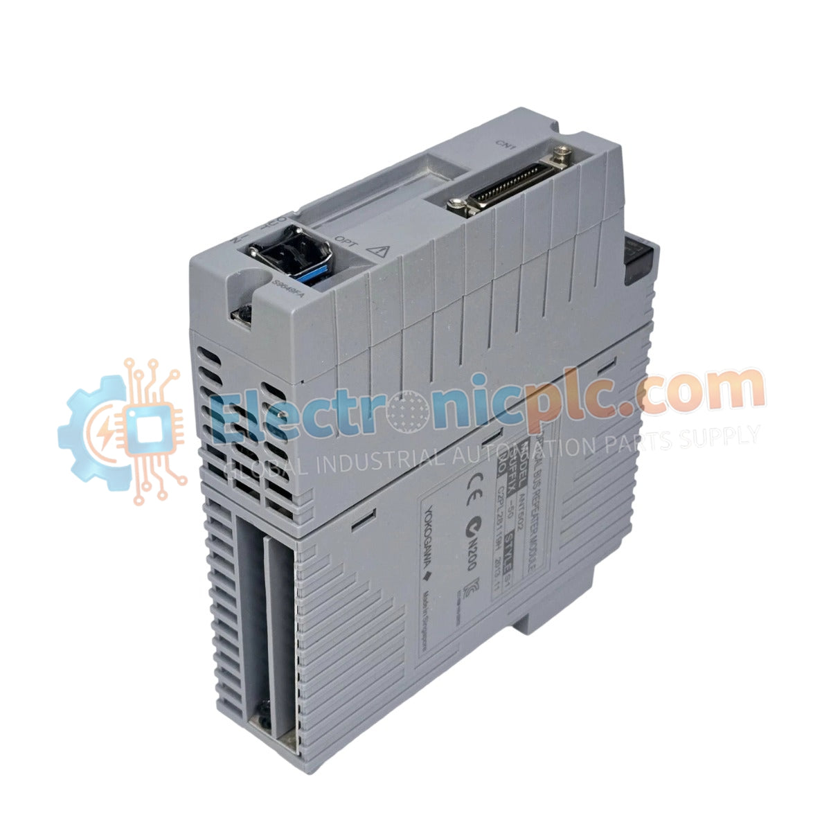

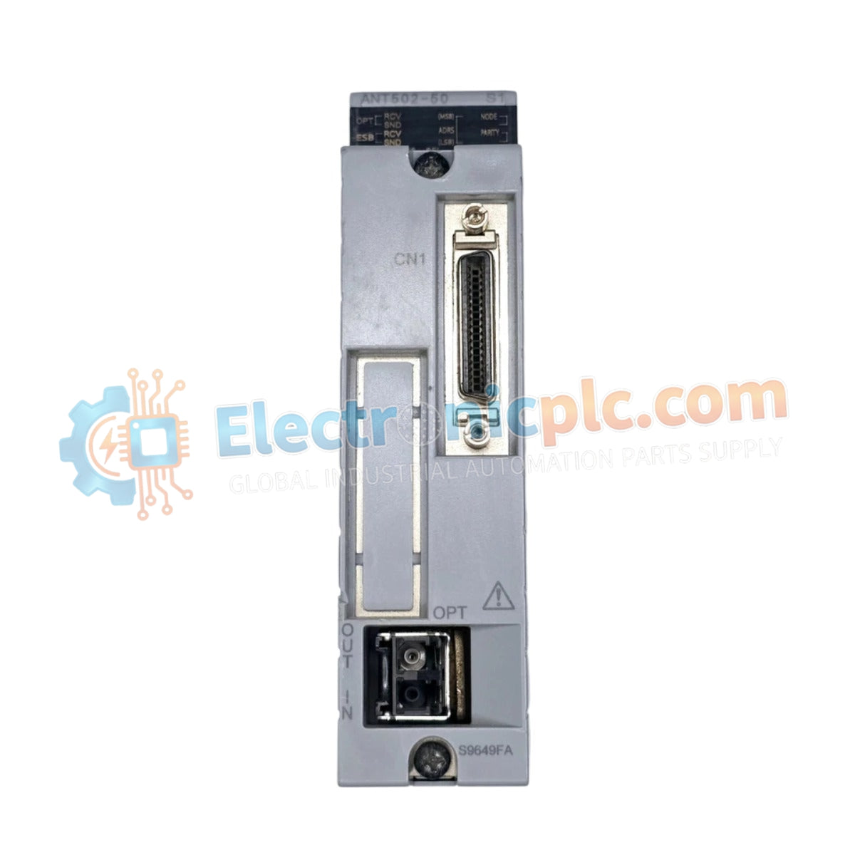
The Yokogawa ANT401-5E, also cataloged as the ANT401-5E Optical ESB Bus Module, operates as a dedicated hardware component for extending ESB bus signal transmission ranges via optical conversion within DCS control networks.
| Parameter | Specification |
|---|---|
| Model | ANT401-5E |
| Brand | Yokogawa |
| Origin | Japan |
| Weight | 0.5 kg |
| Dimensions | 200 x 50 x 30 mm |
| Operating Temp | -20 deg C to +60 deg C |
| Power Consumption | 24 V DC system load |
| Transmission Distance | Up to 5 km |
| Communication Interface | Optical ESB bus |
The ANT401-5E module facilitates the conversion of electrical ESB bus signals into optical pulses to overcome the distance limitations inherent in copper-based communication. By utilizing fiber-optic media, this module provides inherent galvanic isolation between interconnected ESB nodes, effectively eliminating ground loop interference and protecting the control architecture from surge voltages common in long-distance inter-cabinet cabling. The module maintains deterministic communication timing, ensuring that data packets between the Field Control Unit (FCU) and remote nodes remain within acceptable latency thresholds for real-time process control.
Q: Does the ANT401-5E require specific fiber-optic cable types?
A: Yes. The module is calibrated for standardized optical fiber specifications compatible with Yokogawa ESB bus standards. Ensure the fiber core and cladding diameters meet the installation requirements provided in the system integration manual to minimize signal attenuation.
Q: Is the optical link status monitored by the control system?
A: Yes. The module provides diagnostic feedback via the ESB bus interface, allowing the system controller to monitor link integrity and detect optical power degradation or cable breaks in real time.


