My Cart
0 items
Genuine Automation Parts | Worldwide Express Delivery | 12-Month Warranty — [GET A QUOTE]

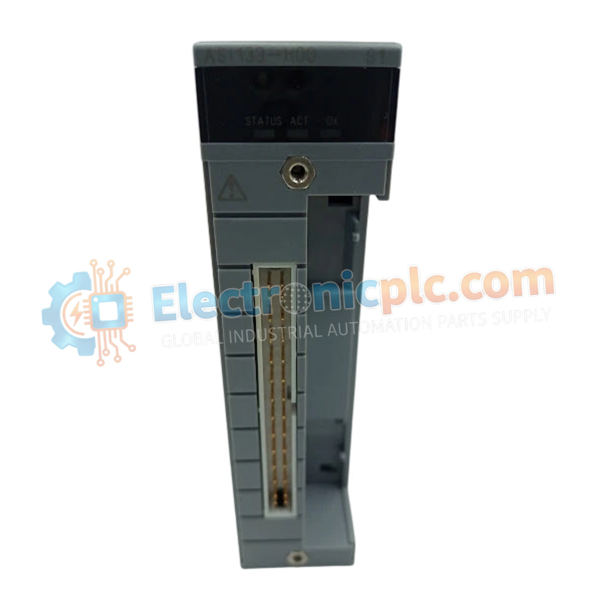
Configured for precise signal conversion in CENTUM VP DCS platforms, the Yokogawa ASI533-S00/SS3S0 (ASI533-S00 Analog Output Module) provides direct electrical execution of control commands to field-mounted actuators and valves.
Availability: In stock
Reliable Worldwide Delivery
30-Day Money-Back Guarantee
Need more details? Read our fullShipping PolicyandRefund Policy.
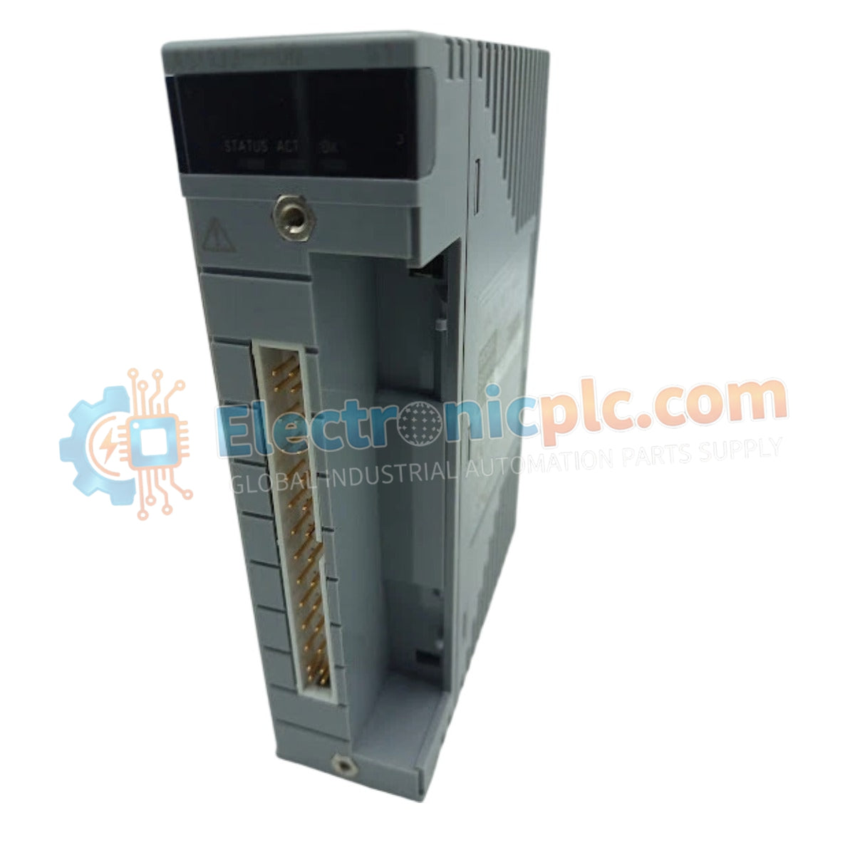
Configured for precise signal conversion in CENTUM VP DCS platforms, the Yokogawa ASI533-S00/SS3S0 (ASI533-S00 Analog Output Module) provides direct electrical execution of control commands to field-mounted actuators and valves.
| Parameter | Specification |
|---|---|
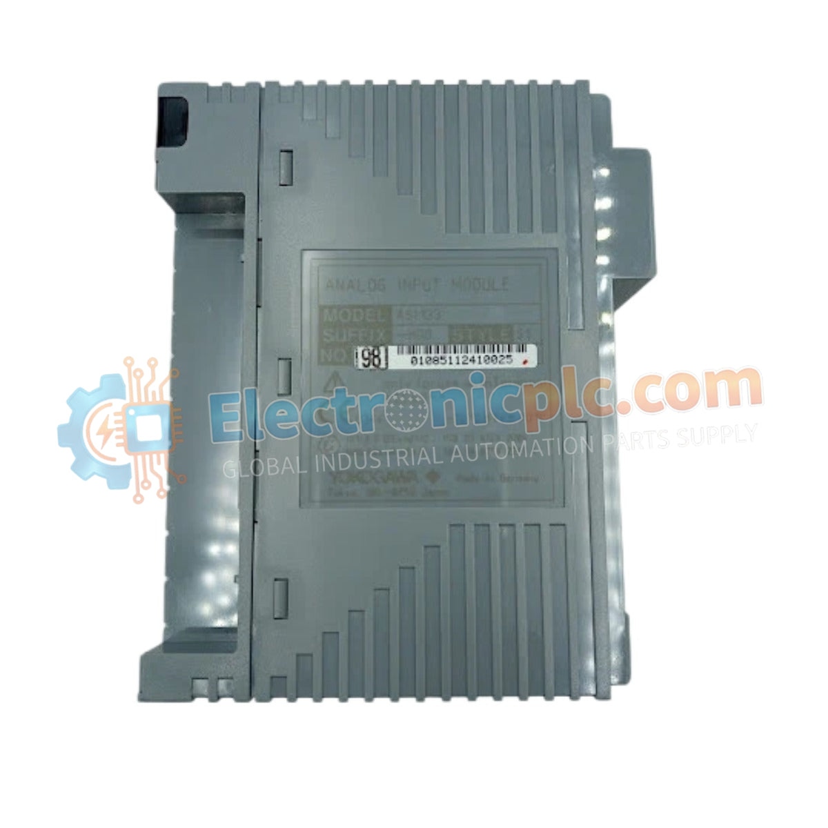
| Model | ASI533-S00 / SS3S0 |
| Brand | Yokogawa |
| Origin | Japan |
| Weight | 0.30 kg |
| Dimensions | 282 mm (W) x 210 mm (H) x 20 mm (D) |
| Operating Temp | Not specified (Standard industrial limits apply) |
| Power Consumption | 150 mA (5 V DC); 350 mA (24 V DC) |
| Output Channels | 8 Channels |
| Output Signal | 4 to 20 mA DC |
| Load Resistance | 0 to 750 Ohm at 20 mA; 0 to 600 Ohm at 23 mA |
| Response Time | 100 ms (Step response) |
| Update Period | 10 ms |
| Isolation | 1500 V AC |
The module facilitates seamless integration within Yokogawa distributed control architectures by supporting the 4-20 mA HART loop protocol. Each of the 8 channels features independent galvanic isolation, ensuring channel-to-channel isolation and minimizing common-mode interference during critical valve positioning tasks. The inclusion of HART communication allows for remote configuration and diagnostic data acquisition from smart field devices without interrupting the primary control loop.
Q: Does the ASI533-S00 support hot-swapping during active DCS operation?
A: Operation procedures for hot-swapping are subject to the specific base plate and system bus configuration of the CENTUM VP rack. Always ensure the system is in a redundant state if required by the cabinet safety protocol before module extraction.
Q: How is the load resistance affected when operating at the maximum 23 mA output?
A: The allowable load resistance reduces from 750 Ohm to 600 Ohm when the output current reaches the 23 mA threshold to maintain signal linearity and prevent output stage saturation.
Q: Is external power required for the 4-20 mA output loops?
A: The module is designed to provide active current signals. Ensure that field wiring complies with the specified loop resistance limits to prevent voltage drop issues at the actuator interface.


