My Cart
0 items
Genuine Automation Parts | Worldwide Express Delivery | 12-Month Warranty — [GET A QUOTE]

Configured for multi-range signal conditioning in industrial control networks, the Yokogawa ASR133-S00/SR3S0 (ASR133-S00/SR3S0 Analog Signal Processing Module) provides direct physical conversion of voltage and current inputs for integration into DCS...
Availability: Low stock: 99 left
Reliable Worldwide Delivery
30-Day Money-Back Guarantee
Need more details? Read our fullShipping PolicyandRefund Policy.

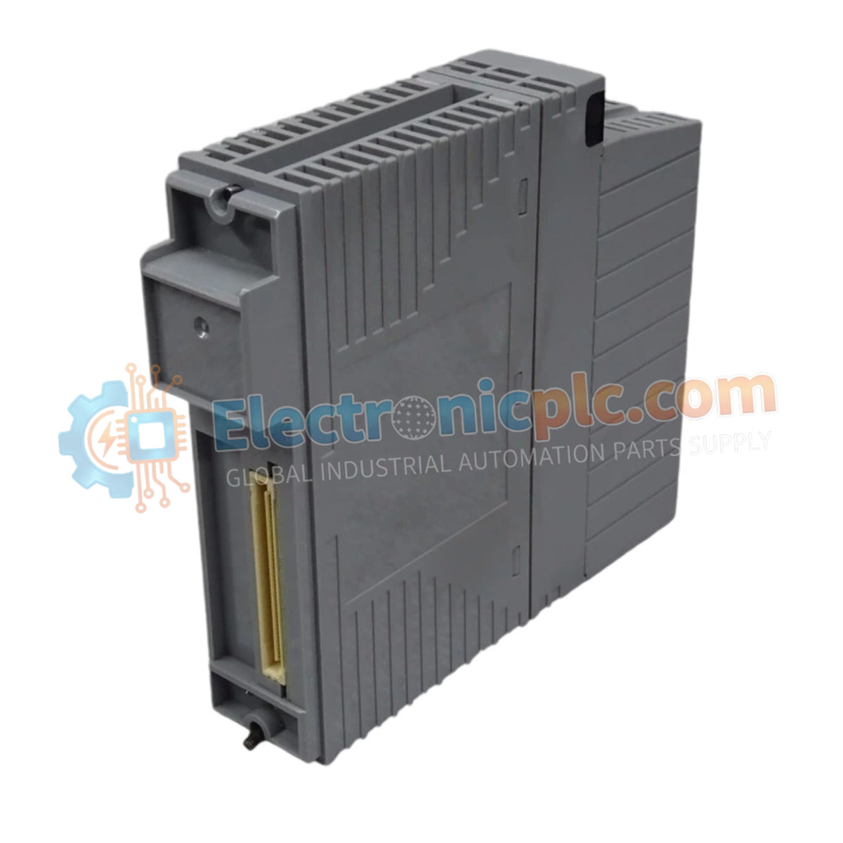
Configured for multi-range signal conditioning in industrial control networks, the Yokogawa ASR133-S00/SR3S0 (ASR133-S00/SR3S0 Analog Signal Processing Module) provides direct physical conversion of voltage and current inputs for integration into DCS processing platforms.
| Parameter | Specification |
|---|---|
| Model | ASR133-S00/SR3S0 |
| Brand | Yokogawa |
| Origin | Japan |
| Weight | 0.5 kg |
| Dimensions | 100 mm x 90 mm x 25 mm |
| Operating Temp | -10 deg C to +60 deg C |
| Power Consumption | 24 VDC (±10%) |
| Input Channels | 8 channels |
| Input Ranges | 0-10 V, +/-10 V, 0-20 mA, 4-20 mA |
The ASR133-S00/SR3S0 utilizes per-channel isolation circuitry to prevent common-mode noise propagation between disparate field loops. This architecture ensures that high-impedance voltage signals and low-impedance current signals remain galvanically isolated from the module backplane, maintaining data integrity during high-speed sampling. The module employs cold junction compensation (CJC) logic where applicable to ensure absolute measurement accuracy in fluctuating thermal environments.
Q: Does this module support field-side power for 4-20 mA loop-powered transmitters?
A: The ASR133-S00/SR3S0 is designed to receive active or passive signals. Verify the loop configuration requirements; if using 2-wire transmitters, ensure the loop power source is correctly integrated according to the module terminal wiring diagram to avoid over-current conditions.
Q: Can the input range be changed via software configuration for all 8 channels?
A: The ASR133-S00/SR3S0 supports configurable input ranges, but physical hardware jumpers or specific software parameters must be verified per channel. Consult the engineering system configuration manual for the exact mapping and software-defined range limits.

