My Cart
0 items
Genuine Automation Parts | Worldwide Express Delivery | 12-Month Warranty — [GET A QUOTE]

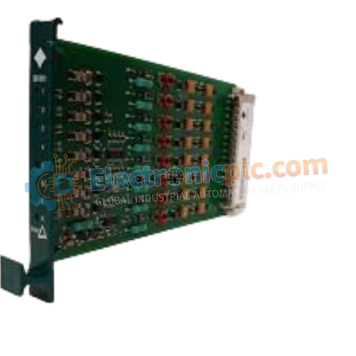
Configured for safety-critical signal acquisition, the Yokogawa DI-511-05 (DI-511 Digital Input Module) provides direct physical/electrical execution of 8-channel fail-safe signal conversion to ProSafe-SLS logic levels.
| Parameter | Specification |
|---|---|
| Model | DI-511-05 |
| Brand | Yokogawa |
| Origin | Japan |
| Weight | 0.11 kg |
| Dimensions | Standard PLC I/O card footprint |
| Operating Temp | Standard industrial range |
| Power Consumption | System-dependent load |
| Input Channels | 8 discrete channels |
| Input Voltage | 24 VDC |
| Status Indicator | Red LED indicators per channel |
The DI-511-05 functions as a dedicated hardware component for converting discrete field inputs into compatible logic signals for the ProSafe-SLS platform. The module utilizes fail-safe circuit design, ensuring that in the event of component failure or input power loss, the module defaults to a safe state. Each of the 8 input channels is equipped with dedicated red LED indicators to provide real-time visual confirmation of logic states, which is essential for rapid on-site troubleshooting. As a critical SIS component, the input stages incorporate electrical protection to maintain signal integrity against common-mode noise and transients.
Q: What defines the fail-safe behavior of the DI-511-05?
A: The module is designed to transition to a known "safe" output state when the input signal is interrupted or the internal logic detects an out-of-range condition, effectively preventing hazardous false-on triggers.
Q: Are the red LEDs indicative of input status or module health?
A: The red LEDs represent the state of the individual input channels. An illuminated LED indicates that the corresponding input threshold has been met, while an extinguished LED signifies an OFF state or a potential loss of input signal.