My Cart
0 items
Genuine Automation Parts | Worldwide Express Delivery | 12-Month Warranty — [GET A QUOTE]

Configured for high-density modular distribution in FA-M3 control networks, the Yokogawa F3BU13-0N/D2 (F3BU13-0N/D2 Base Unit) provides direct physical and backplane electrical execution for system processors and I/O integration across the...
Availability: In stock
Reliable Worldwide Delivery
30-Day Money-Back Guarantee
Need more details? Read our fullShipping PolicyandRefund Policy.


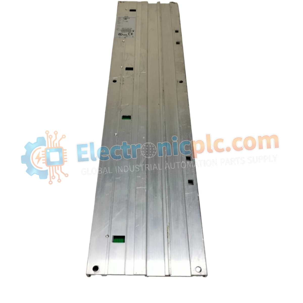
Configured for high-density modular distribution in FA-M3 control networks, the Yokogawa F3BU13-0N/D2 (F3BU13-0N/D2 Base Unit) provides direct physical and backplane electrical execution for system processors and I/O integration across the FA-M3 platform.
| Parameter | Specification |
|---|---|
| Model | F3BU13-0N/D2 |
| Brand | Yokogawa |
| Origin | Japan |
| Weight | 1.52 kg |
| Dimensions | Standard FA-M3 13-slot form factor |
| Operating Temp | 0 to 55 deg C |
| Power Consumption | Dependent on module configuration |
| Slot Capacity | 13 slots total |
The F3BU13-0N/D2 serves as the mechanical and electrical interface for Yokogawa FA-M3 series modules, supporting diverse process control requirements. The architecture provides internal signal routing optimized for 4-20 mA HART loop protocol compatibility within the rack environment. Proper integration ensures robust channel-to-channel isolation performance across the installed I/O modules, maintaining signal integrity in proximity to field instrumentation. When configured for complex process loops, the backplane maintains electrical stability for connected signal conditioning and control components.
Q: Does the F3BU13-0N/D2 support hot-swapping of modules?
A: No. Standard FA-M3 base units are not rated for hot-insertion or hot-removal of modules. The system must be de-energized to prevent electrical faults on the backplane bus during installation or module maintenance.
Q: What are the grounding requirements for this base module?
A: The chassis must be connected to a low-impedance earth ground to ensure effective noise immunity and operator safety. Use the designated grounding terminal on the unit frame, ensuring the connection is free of oxidation.


