
My Cart
0 items
Genuine Automation Parts | Worldwide Express Delivery | 12-Month Warranty — [GET A QUOTE]

Configured for serial data exchange in FA-M3 control networks, the YOKOGAWA F3LC11-2F (F3LC11 PC Link Module) provides direct physical/electrical execution of protocol-based communication between controllers and external host devices.
Availability: In stock
Reliable Worldwide Delivery
30-Day Money-Back Guarantee
Need more details? Read our fullShipping PolicyandRefund Policy.


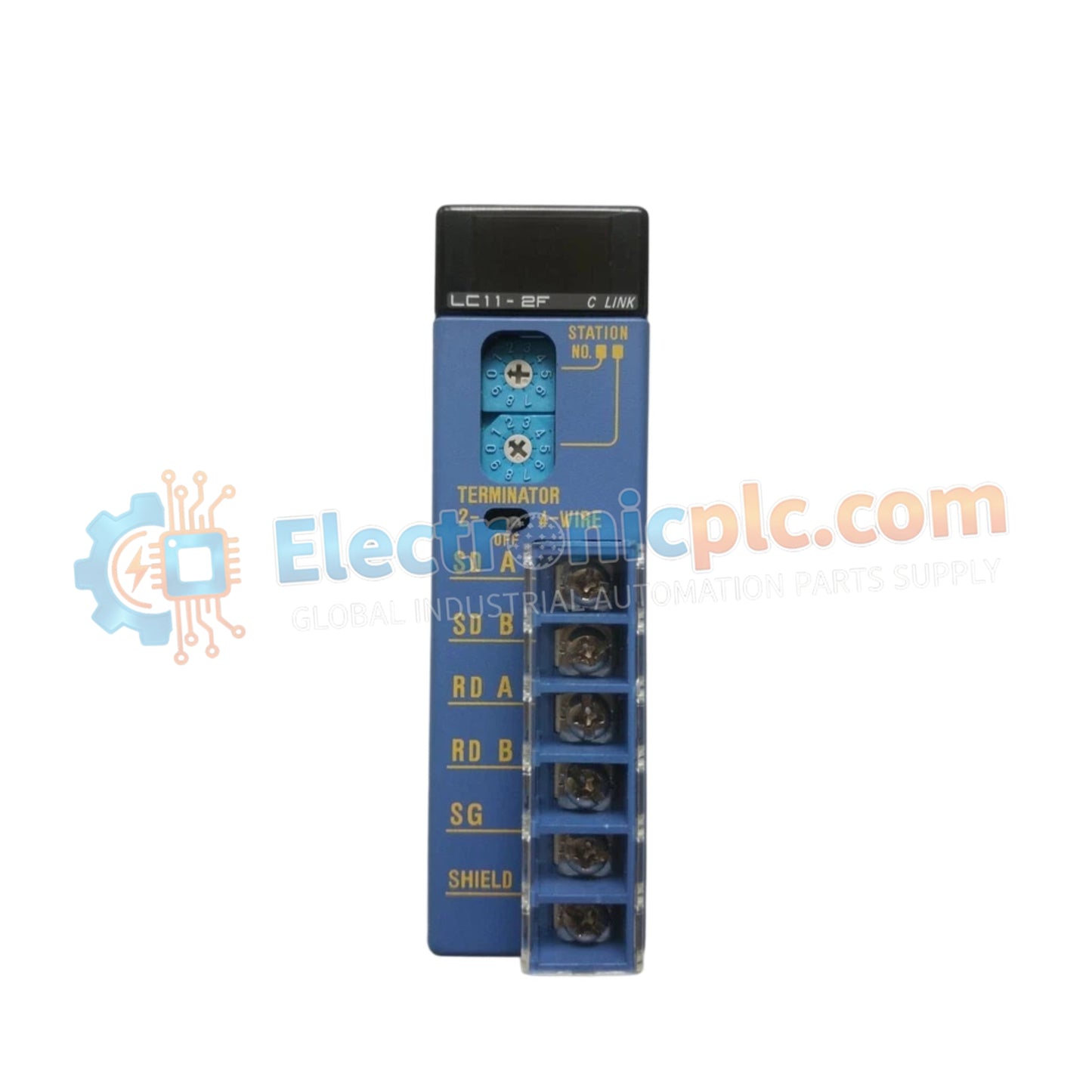
Configured for serial data exchange in FA-M3 control networks, the YOKOGAWA F3LC11-2F (F3LC11 PC Link Module) provides direct physical/electrical execution of protocol-based communication between controllers and external host devices.
| Parameter | Specification |
|---|---|
| Model | F3LC11-2F |
| Brand | YOKOGAWA |
| Origin | Japan |
| Weight | 0.2 kg |
| Dimensions | Standard FA-M3 base unit module form factor |
| Operating Temp | 0 deg C to 55 deg C |
| Power Consumption | 0.5 A (5 V DC) |
| Interfaces | RS-232C, RS-422A, RS-485 |
| Baud Rate | Up to 115.2 kbps |
| Max Connections | 32 units (via RS-422A/485) |
The F3LC11-2F utilizes a proprietary FA-M3 serial protocol to facilitate deterministic data exchange across the module backplane. This interface is engineered for I/O density scaling, allowing the controller to manage communication buffers without degrading scan-time performance. The module supports firmware flash compatibility to accommodate protocol updates and configuration adjustments, ensuring that the serial communication link maintains high-throughput integrity even when scaled to the maximum limit of 32 connected network nodes.
Q: Can the RS-485 interface be configured for multi-drop communication?
A: Yes, the F3LC11-2F supports multi-drop configurations using the RS-422A/485 interface. Up to 32 FA-M3 units can be daisy-chained, provided that the physical layer is properly biased and terminated at both extremities of the bus.
Q: Is the communication protocol accessible to third-party SCADA software?
A: Yes, the module uses standard ASCII-based communication sequences. Third-party host devices can interface with the module by mapping register addresses according to the FA-M3 PC Link protocol memory map.


