
My Cart
0 items
Genuine Automation Parts | Worldwide Express Delivery | 12-Month Warranty — [GET A QUOTE]

Configured for seamless device integration in FA-M3 PLC platforms, the YOKOGAWA F3LC51-2N (F3LC51 UT Link Communication Module) provides direct physical/electrical execution for temperature controller data exchange. This hardware...
Availability: In stock
Reliable Worldwide Delivery
30-Day Money-Back Guarantee
Need more details? Read our fullShipping PolicyandRefund Policy.


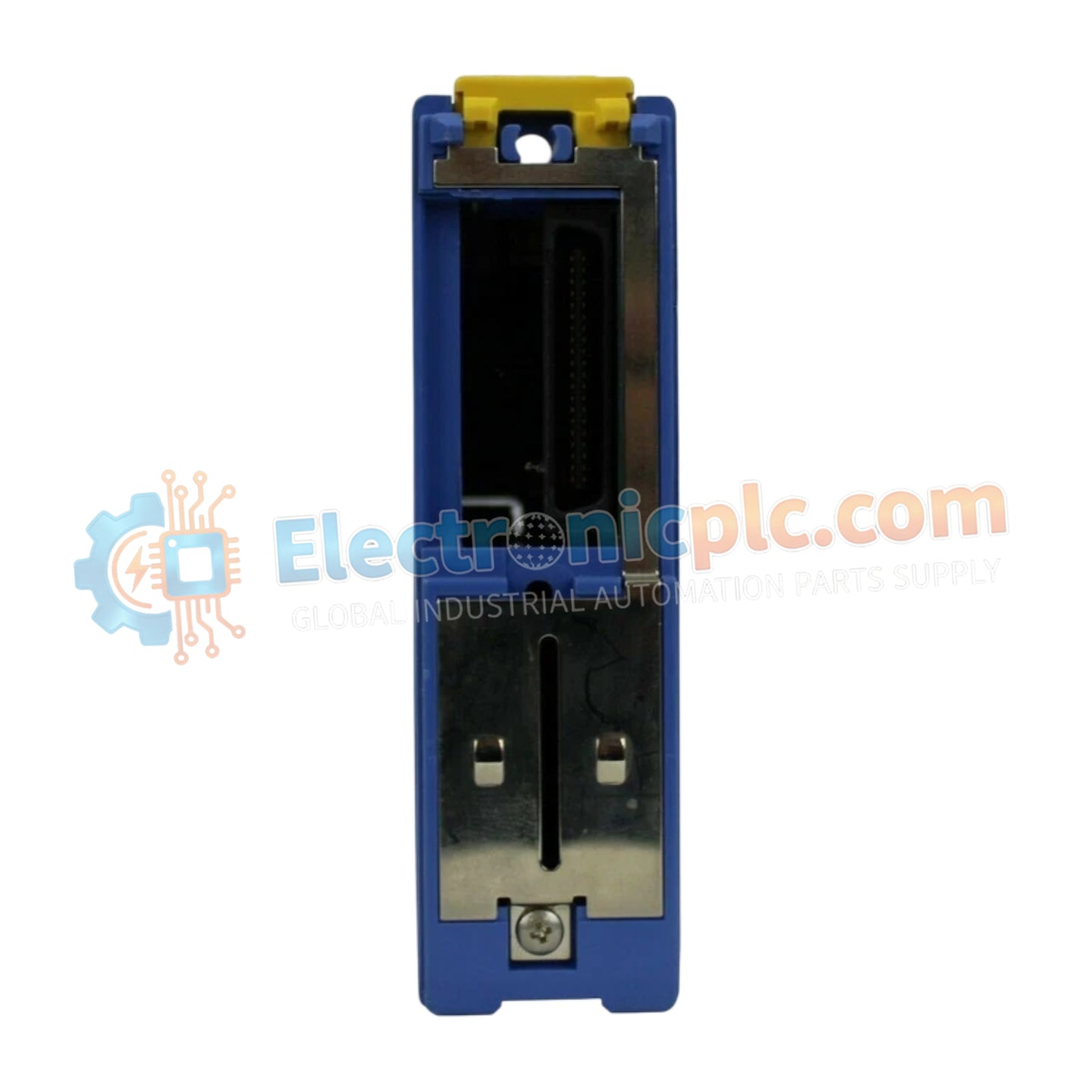
Configured for seamless device integration in FA-M3 PLC platforms, the YOKOGAWA F3LC51-2N (F3LC51 UT Link Communication Module) provides direct physical/electrical execution for temperature controller data exchange. This hardware component manages automated register read/write operations without the requirement for custom communication programming.
The F3LC51-2N is defined by the following configuration attributes:
F3: Series prefix denoting compatibility with the Yokogawa FA-M3 backplane architecture.
LC: Communication module function designation.
51: Indicates the specific UT Link interface generation.
-2N: Specifies the port configuration and network interface standard.
| Parameter | Specification |
| Model | F3LC51-2N |
| Brand | YOKOGAWA |
| Origin | Singapore |
| Weight | 0.15 kg (0.34 lbs) |
| Dimensions | Standard Module Enclosure |
| Operating Temp | 0 deg C to 55 deg C |
| Power Consumption | 5 V DC (Internal Logic) |
| Max Connected Stations | 32 devices |
| Network Ports | 1 x RS-422/RS-485 |
| Max Cable Length | 1200 meters |
The F3LC51-2N utilizes high-speed backplane bus communication velocity to interface between the FA-M3 CPU and external field instruments. By utilizing the UT Link and PC Link protocols, the module ensures deterministic data exchange, refreshing registers automatically. This hardware-level automation reduces CPU scan load and ensures consistent data timing for up to 32 remote stations across RS-485 cabling.
Q: Can the F3LC51-2N be configured to communicate with non-Yokogawa instruments?A: The module is optimized for UT-compatible instruments. While it supports standard PC Link protocol commands, communication with third-party devices requires confirmation of protocol compatibility and command set matching.
Q: Is this module capable of supporting hot-swapping on the FA-M3 rack?A: No, the module does not support hot-swapping. Ensure the PLC system power is disconnected before installing or removing the F3LC51-2N to avoid electrical damage to the backplane pins.
Mount the module securely in the FA-M3 base unit. Ensure the rear backplane connectors are fully engaged and the retention screws are tightened.
For RS-485/RS-422 connections, use shielded, twisted-pair cable. Ensure the cable length does not exceed 1200 meters to maintain signal integrity and communication speed.
Terminate the bus at both physical ends using appropriate resistors to match line impedance and prevent signal reflections.
Ground the communication cable shield at a single point to prevent ground loops, especially when devices are powered from different sources.
Configure the station addresses and communication parameters on the connected field devices to match the settings defined in the PLC software registers.


