
My Cart
0 items
Genuine Automation Parts | Worldwide Express Delivery | 12-Month Warranty — [GET A QUOTE]

The YOKOGAWA F3SP28-3N, also cataloged as the F3SP28 CPU Module, operates as a dedicated hardware component for high-speed sequence control and ladder logic execution within FA-M3 PLC platforms.
Availability: In stock
Reliable Worldwide Delivery
30-Day Money-Back Guarantee
Need more details? Read our fullShipping PolicyandRefund Policy.


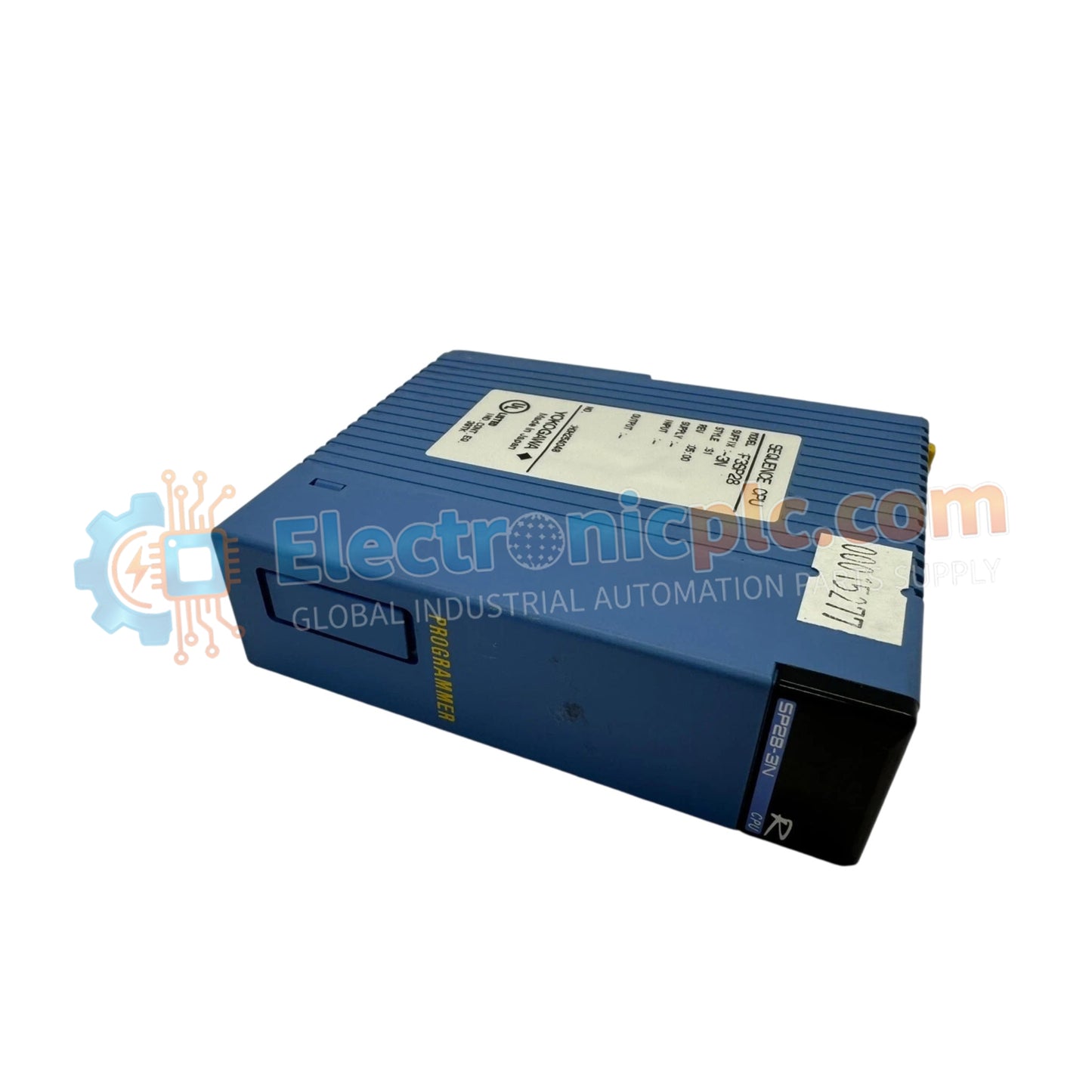
The YOKOGAWA F3SP28-3N, also cataloged as the F3SP28 CPU Module, operates as a dedicated hardware component for high-speed sequence control and ladder logic execution within FA-M3 PLC platforms.
| Parameter | Specification |
|---|---|
| Model | F3SP28-3N |
| Brand | YOKOGAWA |
| Origin | Japan |
| Weight | 0.15 kg |
| Dimensions | 28.9 mm x 100 mm x 83.2 mm |
| Operating Temp | 0 deg C to 55 deg C |
| Power Consumption | 0.5 A (5 V DC) |
| Program Capacity | 30K steps |
| Processing Speed | 0.045 us (Basic instruction) |
| I/O Capacity | 4096 points |
The F3SP28-3N manages internal backplane bus communication velocity to ensure deterministic execution of ladder logic control. The architecture supports I/O density scaling up to 4096 points, allowing the processor to handle extensive process data without exceeding the 1 ms scan time for 6K steps. The module architecture includes firmware flash compatibility to support updates to the instruction set and network communication stack, ensuring that the controller remains synchronized with field-level protocols and external SCADA interface requirements.
Q: Can the instruction processing speed be optimized for specific application requirements?
A: The processor executes instructions at a fixed rate of 0.045 us per basic instruction. System scan time is primarily dependent on the total number of ladder logic steps and the density of I/O points configured on the backplane.
Q: How is the built-in memory protected against power loss?
A: The module utilizes non-volatile memory for program storage. Ensure that the internal backup battery is replaced according to the manufacturer recommended service interval to maintain data retention for volatile register values during extended power outages.


