
My Cart
0 items
Genuine Automation Parts | Worldwide Express Delivery | 12-Month Warranty — [GET A QUOTE]

The YOKOGAWA F3WD64-3P (F3WD64 Digital I/O Module) operates as a dedicated hardware component for mixed signal processing within FA-M3 programmable logic controller platforms. This module provides direct physical/electrical execution for 32 digital inputs...
Availability: In stock
Reliable Worldwide Delivery
30-Day Money-Back Guarantee
Need more details? Read our fullShipping PolicyandRefund Policy.


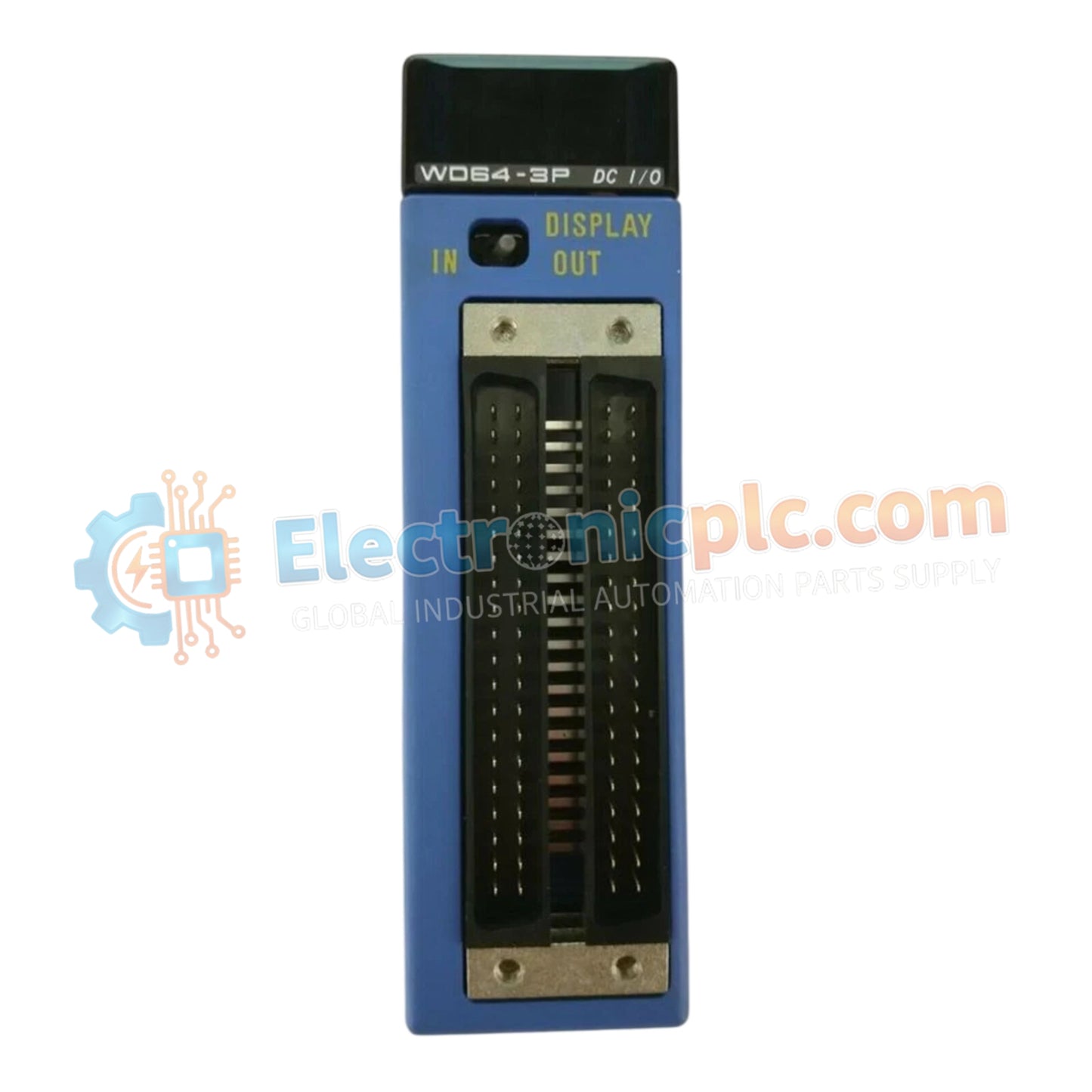
The YOKOGAWA F3WD64-3P (F3WD64 Digital I/O Module) operates as a dedicated hardware component for mixed signal processing within FA-M3 programmable logic controller platforms. This module provides direct physical/electrical execution for 32 digital inputs and 32 transistor sink outputs, facilitating high-density control integration in industrial automation environments.
The F3WD64-3P is designated by the following configuration attributes:
F3: Series prefix denoting compatibility with the Yokogawa FA-M3 backplane architecture.
WD: Digital input/output hybrid function.
64: 64-point total I/O capacity (32 input / 32 output).
3P: Transistor sink output configuration with 24 V DC/12 V DC operating voltage compatibility.
| Parameter | Specification |
| Model | F3WD64-3P |
| Brand | YOKOGAWA |
| Origin | Japan |
| Input Channels | 32 (Photocoupler isolated) |
| Output Channels | 32 (Transistor sink type) |
| Operating Voltage | 24 V DC (20.4–26.4 V) / 12 V DC (10.2–13.2 V) |
| Input Current | 4.1 mA per point |
| Isolation | Photocoupler |
| Mounting | FA-M3 Rack |
The F3WD64-3P utilizes high-speed backplane bus communication to interface between field devices and the FA-M3 controller logic. Input sampling times are configurable, allowing for precise control of response intervals from 0 microseconds up to 1 millisecond. This deterministic performance ensures that state changes are accurately captured and reflected in the PLC memory, maintaining synchronization across complex control sequences without CPU scan delay.
Q: Can the output channels handle inductive loads directly?
A: Transistor sink outputs require external flyback diodes when driving inductive loads (such as solenoid valves or relays) to suppress voltage spikes that could damage the internal output transistors.
Q: Is it possible to use different common lines for different groups of inputs?
A: The module architecture utilizes a common line structure of 8 points per common for both inputs and outputs. You must ensure that the voltage reference for each group of 8 channels is consistent with the module's operating voltage range.
Ensure the power supply is within the specified 10.2 V DC to 26.4 V DC range based on the application requirements before wiring to the terminal block.
Observe the 60% maximum simultaneous input "ON" ratio requirement to manage power dissipation and prevent thermal overload within the module housing.
Use shielded cabling for input signals, particularly those routed near high-noise sources like VFD cables, and terminate the shield to the cabinet protective earth point.
Verify the sink-type wiring polarity; the output common must be connected to the negative side of the 24 V DC or 12 V DC power supply to ensure proper load switching.
After wiring, use the PLC configuration software to map the specific input and output bits and verify functionality through a manual state-forcing test before full system integration.


