
My Cart
0 items
Genuine Automation Parts | Worldwide Express Delivery | 12-Month Warranty — [GET A QUOTE]

Configured for mixed signal processing in FA-M3 control networks, the Yokogawa F3XD08-6F (F3XD08-6F Digital I/O Module) provides direct physical/electrical execution of 8-channel digital input and 8-channel digital output monitoring.
Availability: In stock
Reliable Worldwide Delivery
30-Day Money-Back Guarantee
Need more details? Read our fullShipping PolicyandRefund Policy.


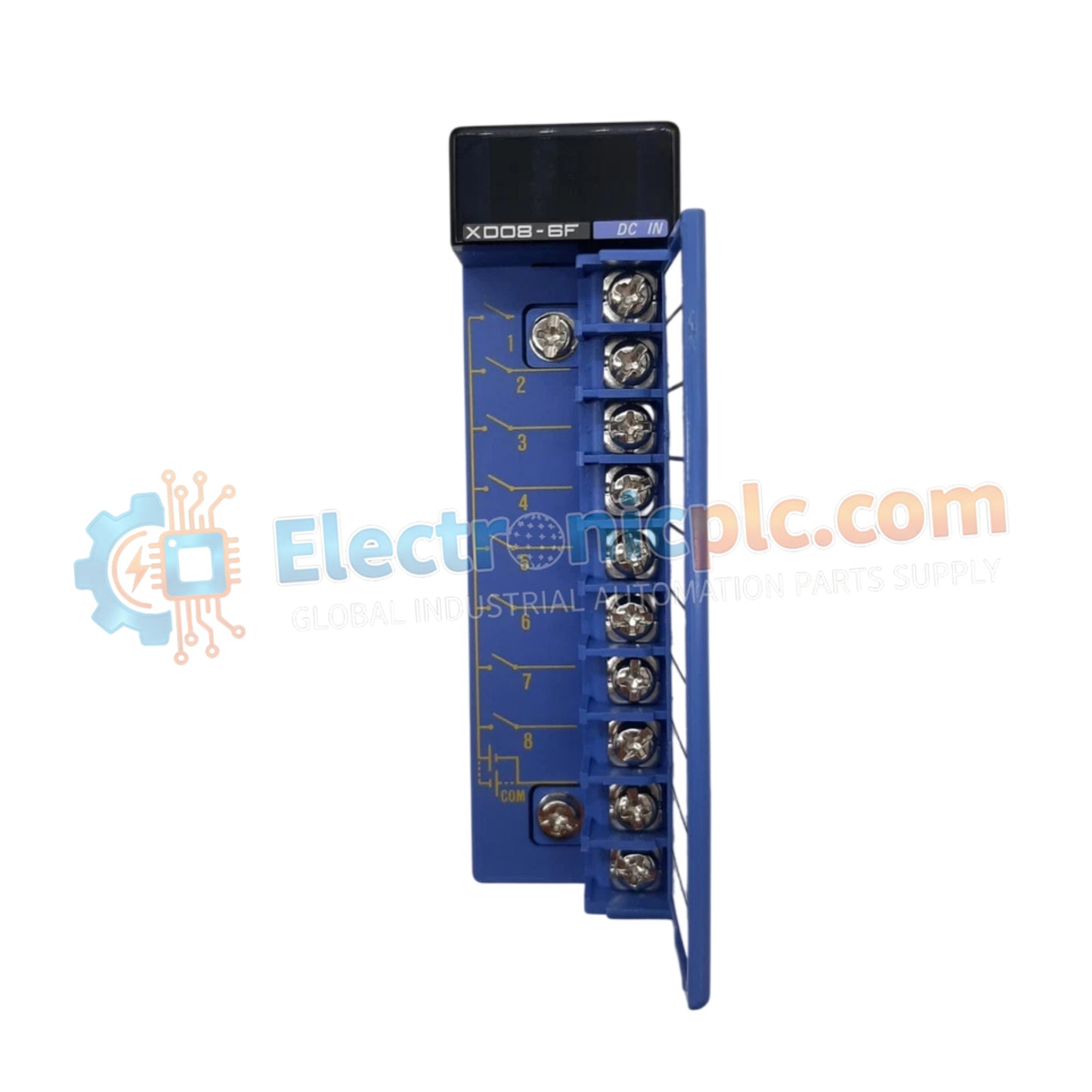
Configured for mixed signal processing in FA-M3 control networks, the Yokogawa F3XD08-6F (F3XD08-6F Digital I/O Module) provides direct physical/electrical execution of 8-channel digital input and 8-channel digital output monitoring.
| Parameter | Specification |
|---|---|
| Model | F3XD08-6F |
| Brand | Yokogawa |
| Origin | japan |
| Weight | 0.2kg |
| Dimensions | 100 mm x 110 mm x 30 mm |
| Operating Temp | 0 deg C to 55 deg C |
| Power Consumption | Not Specified |
| Input Points | 8 points (12-24 VDC) |
| Output Points | 8 points (24 VDC, 0.5 A) |
| Input Current | 4.1 mA (12 VDC), 8.5 mA (24 VDC) |
| Response Time | OFF to ON: 100 us; ON to OFF: 300 us |
The F3XD08-6F module integrates high-speed signal switching within the FA-M3 series architecture. The internal design utilizes photocoupler isolation to decouple field-side logic from the processor backplane, preventing electrical noise from impacting backplane bus communication velocity. The module supports flexible I/O density scaling, allowing for deterministic interaction with field sensors and actuators while maintaining compatibility with industry-standard DIN rail mounting configurations. This electrical isolation ensures that high-speed response times are preserved across the digital loop during active process monitoring.
Q: Does the F3XD08-6F module support hot-swapping while the base unit is energized?
A: No. The F3XD08-6F is not rated for hot-swapping. Ensure the PLC system power is disconnected from the base unit prior to module installation or removal to prevent potential damage to the internal logic circuits.
Q: Can the input type be switched between sink and source modes on a per-point basis?
A: The input circuitry supports sink/source logic, but configuration must be verified against the specific wiring diagram provided in the user manual to ensure compatibility with field-connected sensors.


