
My Cart
0 items
Genuine Automation Parts | Worldwide Express Delivery | 12-Month Warranty — [GET A QUOTE]

Configured for high-frequency signal acquisition in FA-M3 modular controller platforms, the YOKOGAWA F3XH04-3N (F3XH043N High-Speed Input Module) provides direct electrical execution of pulse signal detection and state tracking. The module...
Availability: In stock
Reliable Worldwide Delivery
30-Day Money-Back Guarantee
Need more details? Read our fullShipping PolicyandRefund Policy.


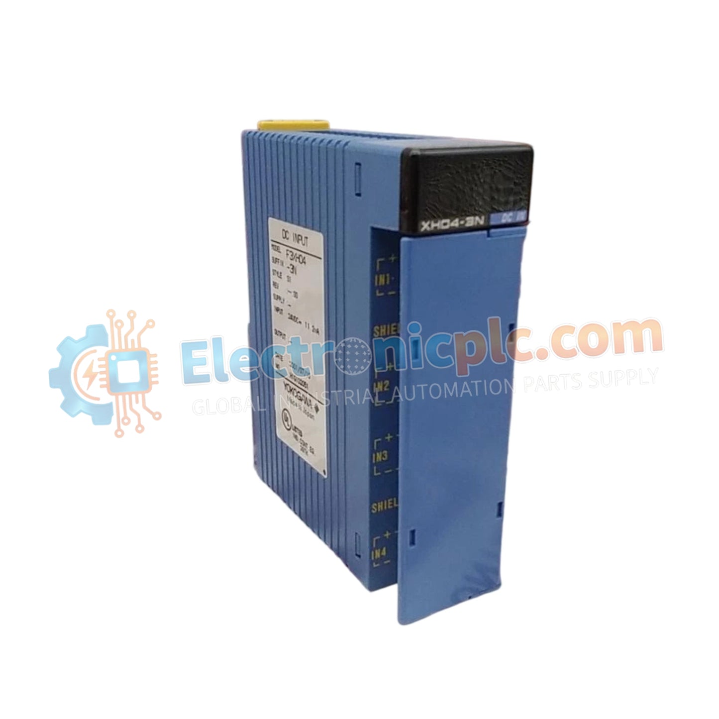
Configured for high-frequency signal acquisition in FA-M3 modular controller platforms, the YOKOGAWA F3XH04-3N (F3XH043N High-Speed Input Module) provides direct electrical execution of pulse signal detection and state tracking. The module serves as a primary interface for high-speed digital sensors, utilizing an integrated pulse catch function to capture transient state changes that occur faster than the host PLC scan cycle.
| Parameter | Specification |
|---|---|
| Model | F3XH04-3N |
| Brand | YOKOGAWA |
| Origin | Japan |
| Weight | 0.3kg |
| Dimensions | Standard PLC module footprint |
| Operating Temp | 0 to 55 deg C |
| Power Consumption | 24 VDC internal logic/field supply |
| Input Type | High-speed digital with pulse catch |
| Channel Count | 32-bit internal registers / 4 channels |
The F3XH04-3N is engineered with a hardware-level pulse catch feature, allowing the module to latch short-duration pulses that would otherwise be missed during the standard PLC scan cycle. This deterministic capture capability ensures that critical input events—such as rapid sensor triggering or encoder pulses—are reliably stored and processed. The input circuitry provides high-speed optoisolation, decoupling the field wiring from the module logic to mitigate the effects of electromagnetic noise and ground potential differences in industrial environments.
Q: Can this module be used to interface with incremental encoders?
A: Yes. The high-speed pulse catch capability allows the module to track state transitions at frequencies exceeding standard digital input modules; however, it is optimized for event-based pulse detection rather than complex quadrature position decoding.
Q: Is the pulse catch function software-configurable?
A: The pulse catch functionality is a hardware-resident feature. It is automatically active for signals routed through the high-speed input channels, ensuring that high-frequency transitions are registered regardless of the PLC software scan duration.


