My Cart
0 items
Genuine Automation Parts | Worldwide Express Delivery | 12-Month Warranty — [GET A QUOTE]

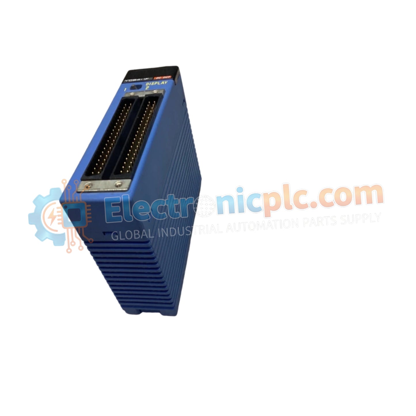
Configured for discrete signal output execution in FA-M3 control systems, the YOKOGAWA F3YD64-1F/Z01 (F3YD64-1F Transistor Output Module) provides direct physical/electrical execution of 64-point logic states.
| Parameter | Specification |
|---|---|
| Model | F3YD64-1F/Z01 |
| Brand | YOKOGAWA |
| Origin | Japan |
| Weight | 0.25 kg |
| Dimensions | 102 mm x 25 mm x 102 mm |
| Operating Temp | Not specified |
| Power Consumption | Not specified |
| Output Points | 64 points |
| Voltage | 24 V DC |
| Current | 0.1 A per point |
The F3YD64-1F/Z01 module manages high-density output requirements through a robust backplane interface, supporting deterministic network cycle times. The module architecture incorporates photocoupler isolation to prevent electrical noise coupling between field-side actuator loads and the internal controller backplane. This isolation design supports a withstanding voltage of 1500 V AC for one minute, ensuring the integrity of the internal logic circuits during transient electrical events or surges within the 24 V DC field bus.
Q: What is the maximum switching frequency for the transistor output channels?
A: The switching speed is limited by the response characteristics of the photocoupler isolation and the connected field load. Refer to the system technical manual for specific cycle time constraints when driving inductive loads.
Q: Are the 64 output channels protected against short-circuit conditions?
A: The module relies on the provided 24 V DC power feed architecture. Ensure appropriate external fusing is installed for each output group to protect the transistor switches from over-current damage caused by field-side wiring faults.