Skip to product information
1 of 3

Yokogawa KS1-05*A Signal Cable

Yokogawa KS1-05*A Signal Cable

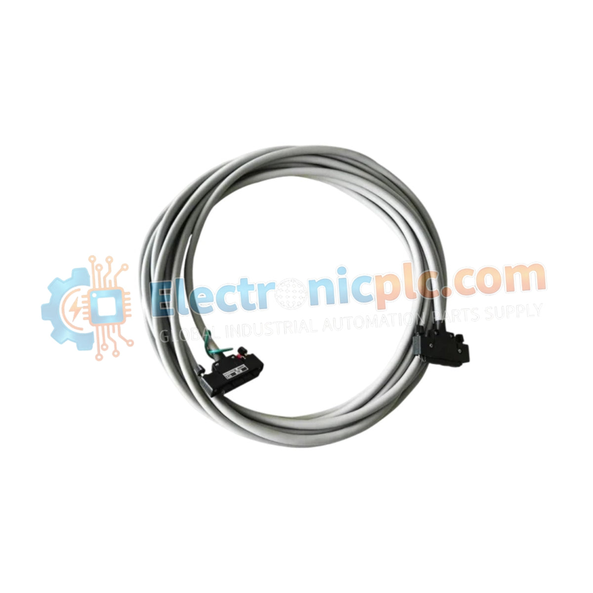
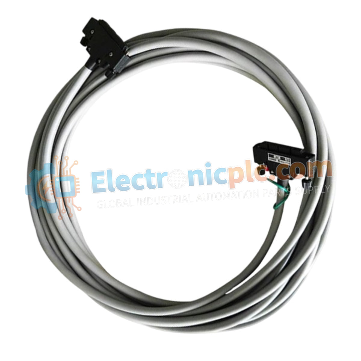
The Yokogawa KS1-05*A, also cataloged as the KS1-05A signal cable, operates as a dedicated hardware component for interconnecting I/O modules to terminal boards within CENTUM VP and ProSafe-RS control systems.

...
26 people are viewing this right now

AvailabilityIn stock

SKU: KS1-05*A
Vendor: Yokogawa
Category: Signal Cable
Related Series:

Shipping & Returns

Reliable Worldwide Delivery

  • Carriers: Shipped via DHL, FedEx, UPS, or USPS.
  • Dispatch: Orders processed in 1-2 business days and dispatched within 3-5 business days.
  • Tracking: Full tracking details provided via email upon shipment.

30-Day Money-Back Guarantee

  • Guarantee: 30-day return window for in-stock, factory-sealed products.
  • Condition: Items must be unopened, unused, and in original packaging.
  • Authenticity: We guarantee 100% original and authentic hardware.

Need more details? Read our fullShipping PolicyandRefund Policy.
Authenticity & Warranty

  • Genuine Guarantee: We supply only 100% original, brand-new, and factory-sealed industrial automation parts.
  • Full Coverage: Every component is backed by a 12-month comprehensive warranty from the date of purchase.
  • Traceability: All products come with original factory documentation and accessories for full industrial compliance.

Technical Support & Sourcing

  • Expert Assistance: Our technical team provides free consultation to help you verify compatibility for DCS and PLC systems.
  • Rare Part Sourcing: Specializing in obsolete and hard-to-find components from Allen-Bradley, Siemens, ABB, HIMA, and more.
  • Bulk Inquiries: Contact us at pambo@5gplc.com for volume pricing or customized project quotes.
View full product details

The Yokogawa KS1-05*A, also cataloged as the KS1-05A signal cable, operates as a dedicated hardware component for interconnecting I/O modules to terminal boards within CENTUM VP and ProSafe-RS control systems.

Suffix Breakdown & Model Matrix

  • KS1: Denotes the series designation for Yokogawa signal cable assemblies.
  • 05: Represents the standard physical cable length of 5 meters.
  • A: Specifies the Style A configuration, dictating the 40-pin to 40-pin connector pinout and specific shielding architecture.

Hardware Specifications

Parameter Specification
Model KS1-05*A
Brand Yokogawa
Origin Japan
Weight 0.85 kg
Dimensions 5 m length
Operating Temp -20 deg C to +70 deg C
Power Consumption Not applicable (Passive component)
Connector Type 40-pin to 40-pin (Style A)
Conductor Material Tinned copper, twisted pair
Bending Radius 100 mm (minimum)

Process Connectivity and Signal Integrity

The KS1-05*A utilizes a specialized shielding configuration designed to maintain signal integrity within industrial environments subject to high electromagnetic interference (EMI). The implementation of EMI-resistant shielding ensures that the 4-20 mA analog or digital discrete signals remain within tolerance levels during transmission from field termination assemblies to the DCS I/O backplane. The PVC flame-retardant outer jacket provides mechanical protection for stationary routing in control cabinets.

Frequently Asked Questions

Q: Can the KS1-05*A cable be extended beyond its 5-meter rating?

A: No. Extending the cable length beyond the manufacturer-specified 5 meters may introduce unacceptable voltage drops or impedance mismatches, potentially causing signal distortion in sensitive analog loops.

Q: Does the Style A connector support hot-swapping of I/O modules?

A: While the cable itself does not prohibit hot-swapping, the I/O modules and terminal boards connected via the KS1-05*A must be designed for hot-plugging. Ensure proper grounding procedures are followed before disconnecting the 40-pin interface.

Field Installation Guidelines

  • Cable Routing: Route signal cables through dedicated cable trays separated from high-voltage power lines and VFD output cabling to minimize inductive noise coupling.
  • Bending Constraints: Ensure that the cable bend radius does not fall below 100 mm during installation to prevent internal conductor fatigue or shielding degradation.
  • Connector Engagement: Verify that the 40-pin connectors are fully seated and that the integrated locking mechanism is engaged to ensure consistent electrical contact.
  • Environmental Shielding: Ensure the cable jacket is free from abrasions. If routing through metal conduits, ensure the cable is not subjected to localized mechanical stress at the conduit entry points.