
My Cart
0 items
Genuine Automation Parts | Worldwide Express Delivery | 12-Month Warranty — [GET A QUOTE]

The YOKOGAWA KS10-07*A, also cataloged as the KS10 Signal Cable, operates as a dedicated hardware component for high-density signal transmission between field interface modules and I/O subsystems within CENTUM VP...
Availability: In stock
Reliable Worldwide Delivery
30-Day Money-Back Guarantee
Need more details? Read our fullShipping PolicyandRefund Policy.
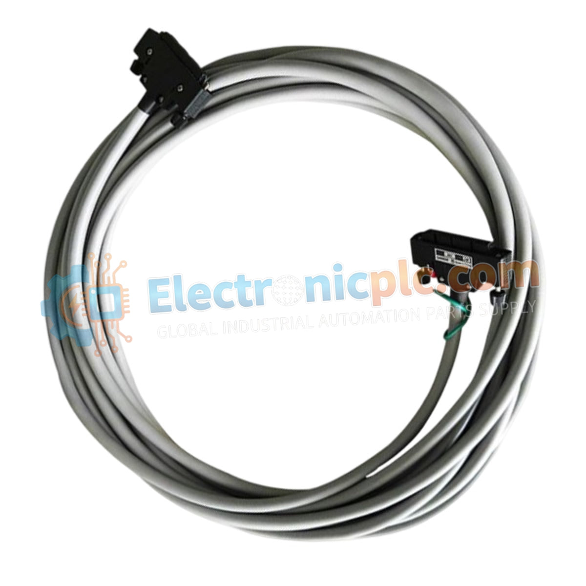
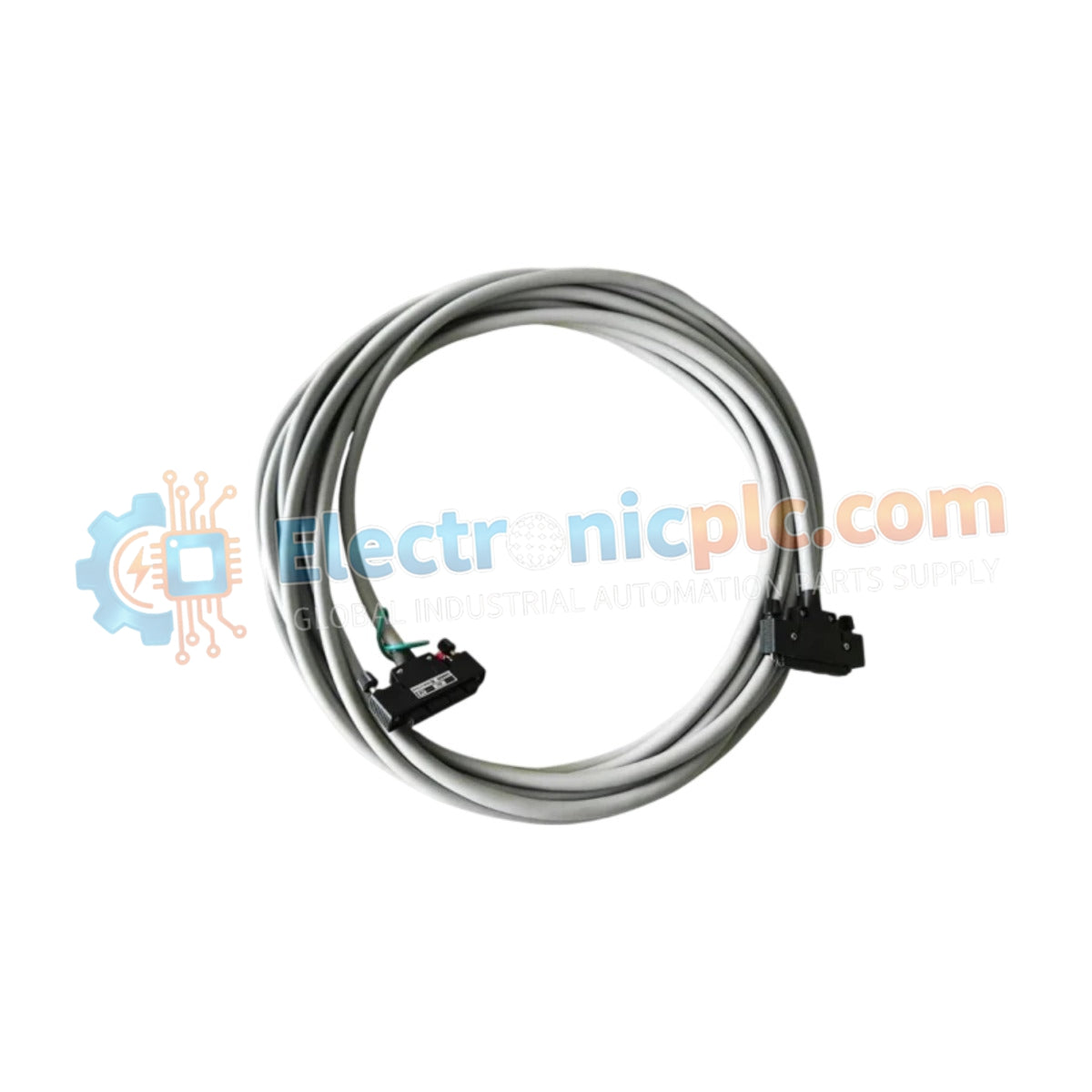
The YOKOGAWA KS10-07*A, also cataloged as the KS10 Signal Cable, operates as a dedicated hardware component for high-density signal transmission between field interface modules and I/O subsystems within CENTUM VP and CS3000 distributed control platforms.
| Model | Suffix / Style Code | Description |
|---|---|---|
| KS10 | 07 | Cable length 7 meters |
| KS10 | *A | Style A |
| Parameter | Specification |
|---|---|
| Model | KS10-07*A |
| Brand | YOKOGAWA |
| Origin | Japan |
| Weight | 1.5 kg |
| Dimensions | 7 meters length |
| Operating Temp | -10 deg C to 60 deg C |
| Power Consumption | N/A (Passive interconnect) |
| Connector Type | 50-pin to 50-pin |
| Operating Voltage | 30 V DC |
The KS10-07*A assembly utilizes a robust EMI/RFI shielded jacket to maintain signal fidelity in electrically dense industrial environments. The internal 50-pin conductor arrangement is specifically wired to support the interface requirements of CENTUM series I/O cards, minimizing crosstalk and signal attenuation across the 7-meter span. By maintaining controlled impedance and proper shield grounding, the cable prevents the ingress of external noise, ensuring that analog and digital signals remain within precise tolerance levels during real-time DCS operations.
Q: Is this cable suitable for use in environments with high electromagnetic interference?
A: Yes, the integrated EMI/RFI shielding is designed to attenuate external noise. Ensure the cable is routed through dedicated instrumentation trays and that the shield drain wire is properly bonded to the system chassis ground to maximize protection.
Q: Can the KS10-07*A be used as a replacement for different Style codes?
A: No. Style codes (e.g., *A vs B) often denote specific wiring or mechanical revisions unique to the module interface. Verify the system documentation for the target I/O module to ensure the KS10-07A pinout is compatible with the required terminal assignment.


