My Cart
0 items
Genuine Automation Parts | Worldwide Express Delivery | 12-Month Warranty — [GET A QUOTE]

The YOKOGAWA KS10-10*A, also cataloged as the KS10-10 Signal Cable, operates as a dedicated hardware component for high-density analog and digital signal interconnection between field terminal blocks and DCS input/output...
Availability: Low stock: 99 left
Reliable Worldwide Delivery
30-Day Money-Back Guarantee
Need more details? Read our fullShipping PolicyandRefund Policy.
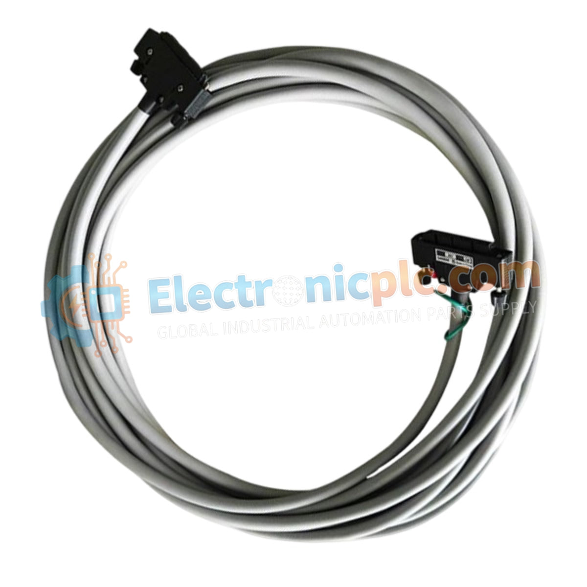
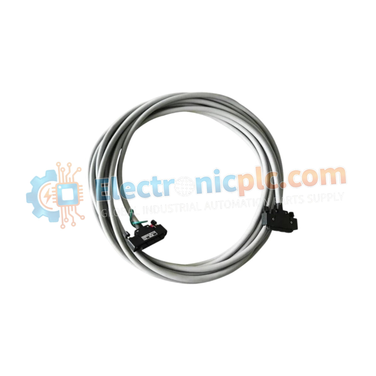
The YOKOGAWA KS10-10*A, also cataloged as the KS10-10 Signal Cable, operates as a dedicated hardware component for high-density analog and digital signal interconnection between field terminal blocks and DCS input/output modules.
| Parameter | Specification |
|---|---|
| Model | KS10-10*A |
| Brand | YOKOGAWA |
| Origin | japan |
| Weight | 2 kg |
| Dimensions | Not Specified |
| Operating Temp | Standard Industrial Range |
| Power Consumption | Passive Component |
| Pin Configuration | 50-pin to 50-pin |
The KS10 series cables are utilized to maintain 4-20 mA HART loop protocol signal integrity between field junction boxes and Yokogawa process control stations. Each cable assembly ensures channel-to-channel isolation by maintaining strict twisted-pair shielding requirements, preventing cross-talk in high-density I/O racks. The cable incorporates cold junction compensation (CJC) path continuity for temperature-sensing loops, ensuring that thermocouple and RTD signal degradation remains within the tolerance of the host controller.
Q: Can the KS10-10*A cable be shortened in the field without compromising the connection integrity?
A: Field modification of the cable length is strictly discouraged, as manual termination of the 50-pin connectors often introduces impedance mismatch and signal noise, which may interfere with high-precision DCS analog loops.
Q: Are these cables shielded against electromagnetic interference (EMI)?
A: Yes, the internal conductors are shielded to suppress induced noise, adhering to industrial standards for DCS signal propagation. Ensure the cable drain wire is connected to the instrument earth at the designated terminal point.


