
My Cart
0 items
Genuine Automation Parts | Worldwide Express Delivery | 12-Month Warranty — [GET A QUOTE]

Configured for high-integrity signal transmission in distributed control systems, the YOKOGAWA KS2-10*B (KS2-10*B Signal Cable) provides direct physical execution of data routing between field control modules and terminal blocks. The...
Availability: In stock
Reliable Worldwide Delivery
30-Day Money-Back Guarantee
Need more details? Read our fullShipping PolicyandRefund Policy.
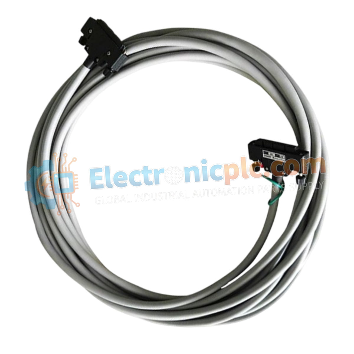
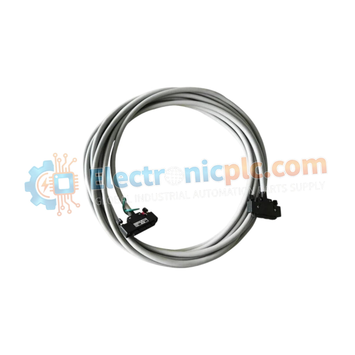
Configured for high-integrity signal transmission in distributed control systems, the YOKOGAWA KS2-10*B (KS2-10*B Signal Cable) provides direct physical execution of data routing between field control modules and terminal blocks. The cable assembly enables multi-channel signal transport across V-net, ER bus, ESB bus, and RIO bus architectures through a high-density interface.
| Parameter | Specification |
|---|---|
| Model | KS2-10*B |
| Brand | YOKOGAWA |
| Origin | Japan |
| Weight | 0.9kg |
| Dimensions | 10 meters length |
| Operating Temp | Standard industrial range |
| Power Consumption | Passive (None) |
| Connector Type | 40-pin to 40-pin |
| Shielding | EMI-resistant |
The KS2-10*B cable is engineered with EMI-resistant shielding to mitigate electromagnetic interference in high-density industrial control environments. While the cable acts as a passive transmission medium, its internal conductor geometry is optimized to maintain low crosstalk and signal attenuation across the full 10-meter span. Channel-to-channel isolation performance is determined by the grounding integrity of the connected control modules and field termination assemblies. The 40-pin interface ensures consistent pin-to-pin continuity for high-density I/O clusters, supporting the bandwidth requirements of standardized DCS signal protocols.
Q: Can this cable be shortened or extended without compromising signal integrity?
A: Modification of the cable length is not recommended. Changing the cable geometry or connector termination can introduce impedance mismatches and negate the EMI shielding effectiveness required for stable DCS communication.
Q: Is this cable suitable for use in high-vibration industrial cabinets?
A: Yes, provided the cable is properly routed and secured using strain relief hardware to prevent tension on the 40-pin connectors. Ensure that connector locking mechanisms are fully engaged to maintain electrical contact.


