
My Cart
0 items
Genuine Automation Parts | Worldwide Express Delivery | 12-Month Warranty — [GET A QUOTE]

Configured for high-integrity signal transmission in industrial control platforms, the YOKOGAWA KS9-20 (KS9-20 PLC Cable) provides direct physical execution of data routing between PLC I/O modules and field terminal blocks....
Availability: In stock
Reliable Worldwide Delivery
30-Day Money-Back Guarantee
Need more details? Read our fullShipping PolicyandRefund Policy.
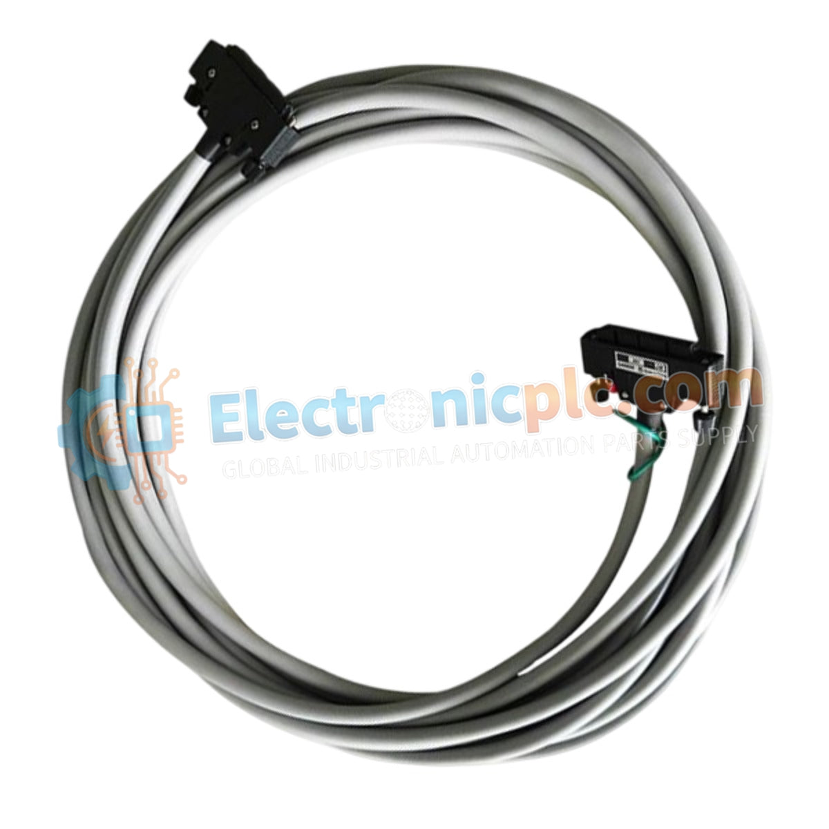
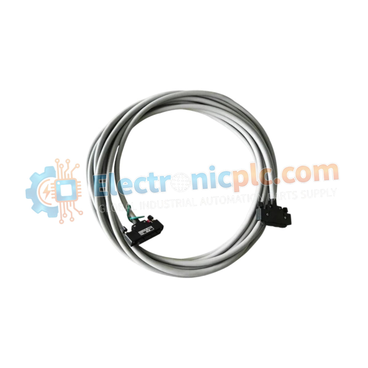
Configured for high-integrity signal transmission in industrial control platforms, the YOKOGAWA KS9-20 (KS9-20 PLC Cable) provides direct physical execution of data routing between PLC I/O modules and field terminal blocks. The cable assembly ensures stable, low-latency signal transport across Yokogawa FA-M3 and distributed control architectures through a high-density, standardized connector interface.
| Parameter | Specification |
|---|---|
| Model | KS9-20 |
| Brand | YOKOGAWA |
| Origin | Japan |
| Weight | 0.9kg |
| Dimensions | Variable length |
| Operating Temp | Standard industrial range |
| Power Consumption | Passive (None) |
| Connector Type | Multi-pin PLC interface |
| Shielding | Industrial-grade EMI protection |
The KS9-20 cable assembly is engineered to maintain signal fidelity in high-density industrial control environments. By utilizing high-conductive copper conductors and industrial-grade insulation, the cable provides reliable path continuity for both analog and digital I/O signals. The integration of EMI-resistant shielding is essential for mitigating inductive noise generated by adjacent high-power drive cabling or AC supply lines, ensuring that data packets remain deterministic and free from parity or corruption errors within the PLC backplane communication cycle.
Q: Is this cable compatible with legacy FA-M3 modules?
A: Yes, the KS9-20 is designed for compatibility with standard FA-M3 I/O terminal interfaces; however, always verify the pinout configuration against the specific module documentation to ensure proper signal mapping.
Q: Can the cable be field-repaired if the connector is damaged?
A: Field repair of the molded connector interface is not recommended. If the connector housing or pin integrity is compromised, the cable assembly should be replaced to prevent intermittent signal faults that could cause erratic I/O behavior.


