My Cart
0 items
Genuine Automation Parts | Worldwide Express Delivery | 12-Month Warranty — [GET A QUOTE]

Configured for precision signal acquisition within industrial automation networks, the Yokogawa NC1AY02-MR (NC1AY02-MR Analog Input Module) provides direct physical and electrical execution of multi-channel analog signal processing.
Availability: In stock
Reliable Worldwide Delivery
30-Day Money-Back Guarantee
Need more details? Read our fullShipping PolicyandRefund Policy.

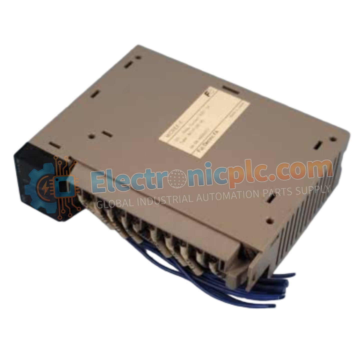
Configured for precision signal acquisition within industrial automation networks, the Yokogawa NC1AY02-MR (NC1AY02-MR Analog Input Module) provides direct physical and electrical execution of multi-channel analog signal processing.
| Parameter | Specification |
|---|---|
| Model | NC1AY02-MR |
| Brand | Yokogawa |
| Origin | Japan |
| Weight | 0.2 kg |
| Dimensions | Standard industrial module profile |
| Operating Temp | -10 deg C to +55 deg C |
| Power Consumption | Backplane dependent |
| Input Channels | Multi-channel configuration |
| Signal Range | Voltage/Current configurable |
| Resolution | 12-bit standard |
The NC1AY02-MR architecture facilitates efficient I/O density scaling within Yokogawa FA-M3 and STARDOM controller nodes. The module manages deterministic input state capture, ensuring that backplane bus communication velocity remains consistent across all active channels. The hardware includes internal circuitry for signal conditioning, allowing for interface flexibility with standard industrial instrumentation. By maintaining galvanic isolation between the field-side inputs and the backplane logic, the module preserves signal integrity in high-EMI environments, preventing state corruption during critical control sequences.
Q: Does the NC1AY02-MR support field-level configuration for different signal ranges?
A: Yes. The module supports selectable input ranges to accommodate various voltage or current inputs; specific configuration is achieved through the system programming software or internal module switch settings depending on the hardware revision.
Q: Can this module be installed in a rack with mixed analog and high-current relay modules?
A: Yes, provided that adequate separation is maintained between high-current wiring and sensitive analog signal cables. It is recommended to segregate output wiring from the analog input terminal block to prevent induced electromagnetic noise.

