My Cart
0 items
Genuine Automation Parts | Worldwide Express Delivery | 12-Month Warranty — [GET A QUOTE]

Configured for high-density signal distribution within PLC architectures, the Yokogawa NC1Y16R-08 (NC1Y16R-08 Digital Output Module) provides direct physical and electrical execution of 16-channel relay-based control state switching.
Availability: In stock
Reliable Worldwide Delivery
30-Day Money-Back Guarantee
Need more details? Read our fullShipping PolicyandRefund Policy.


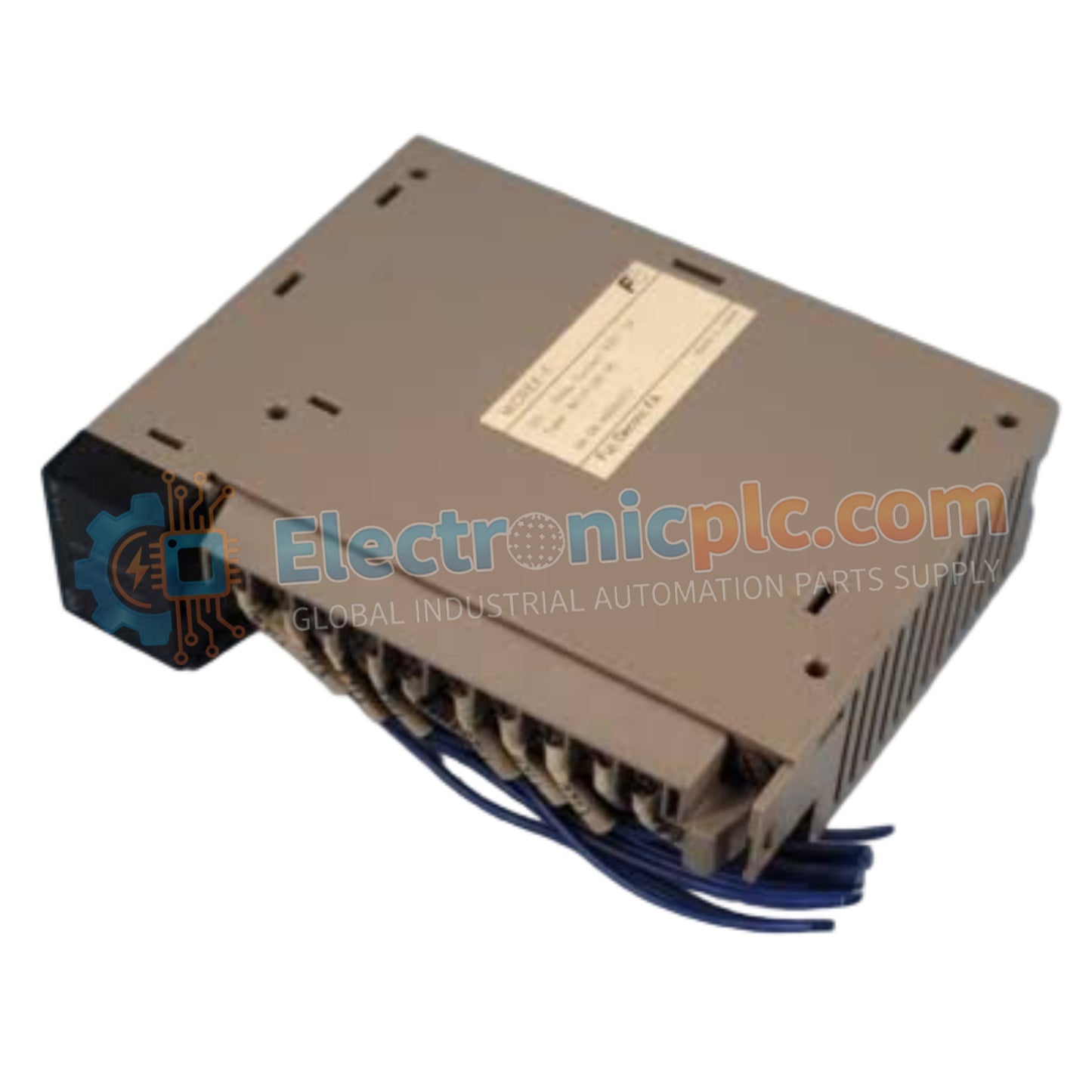
Configured for high-density signal distribution within PLC architectures, the Yokogawa NC1Y16R-08 (NC1Y16R-08 Digital Output Module) provides direct physical and electrical execution of 16-channel relay-based control state switching.
| Parameter | Specification |
|---|---|
| Model | NC1Y16R-08 |
| Brand | Yokogawa |
| Origin | Japan |
| Weight | 0.3 kg |
| Dimensions | 3.8 cm x 13.5 cm x 10.9 cm |
| Operating Temp | Standard industrial range |
| Power Consumption | Backplane dependent |
| Output Points | 16 points |
| Output Voltage | 24 V DC, 200 V AC |
| Relay Capacity | 2 A per point, 8 A per common |
The NC1Y16R-08 architecture is optimized for robust digital control within Yokogawa FA-M3 and STARDOM platforms, facilitating efficient I/O density scaling for relay-based field applications. The module manages deterministic output state propagation, ensuring that backplane bus communication velocity remains synchronized with the master controller. The hardware design features two groups of 8 points, each sharing a common return path, which simplifies wiring in modular cabinet assemblies. By maintaining isolation between the relay coils and the backplane logic, the module prevents potential electrical feedback or transients from impacting the deterministic performance of the control processor.
Q: Are the output relays replaceable in the field if a point fails?
A: No. The relays are integrated into the module circuitry. If a point failure occurs due to relay contact welding or coil fatigue, the entire module must be replaced to maintain the integrity of the safety control loop.
Q: How should the common terminals be configured for mixed-voltage applications?
A: The module supports 8 points per common group. If different voltages or phases are used, ensure they are segregated into separate common groups; never bridge different voltage sources across the same common terminal to prevent hazardous short-circuit conditions.


