My Cart
0 items
Genuine Automation Parts | Worldwide Express Delivery | 12-Month Warranty — [GET A QUOTE]

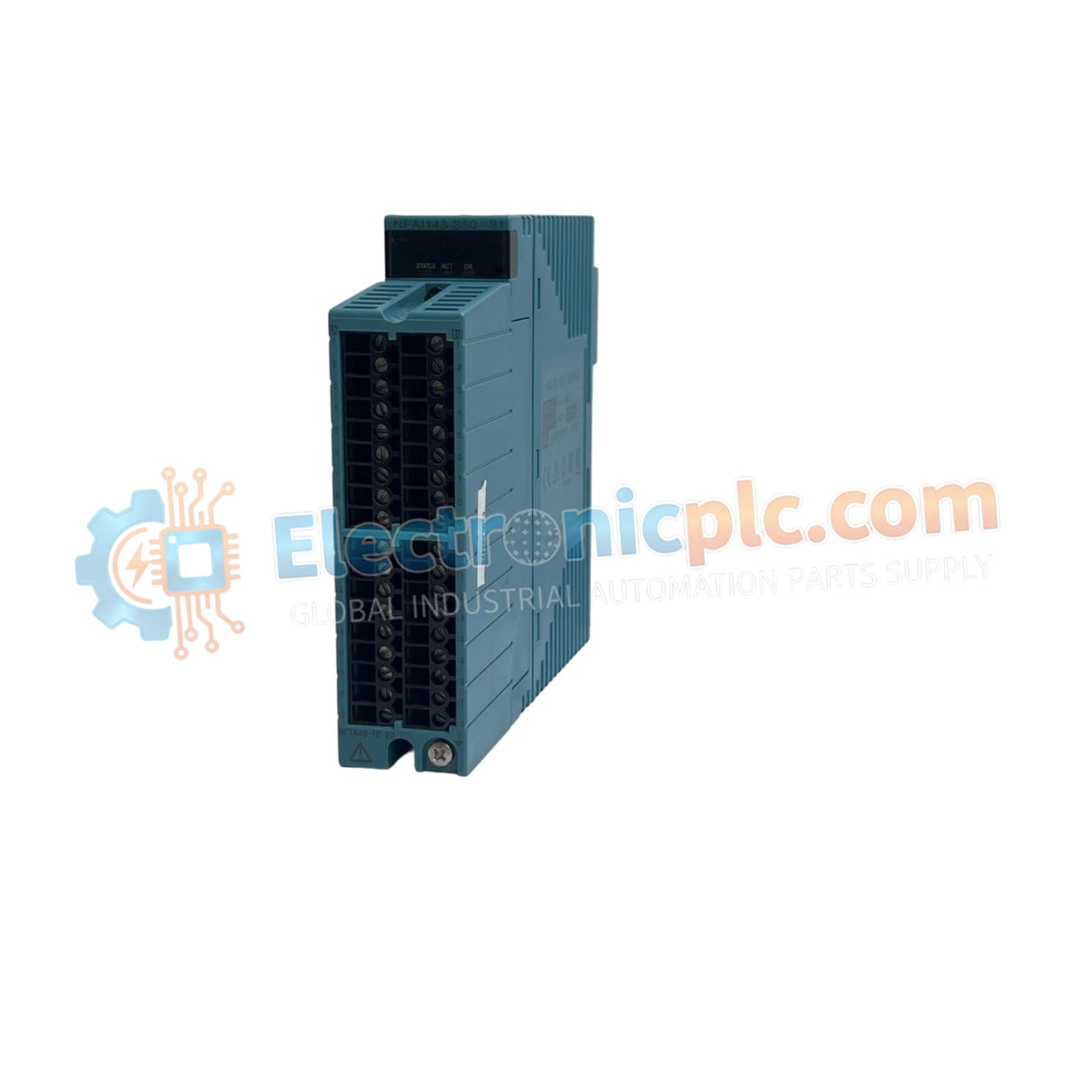
The YOKOGAWA NFAF135-S50 (NFAF135-S50 Pulse Input Module) serves as the primary NFAF135-S50 Pulse Input Module utilized to execute high-speed pulse signal acquisition across CENTUM VP and ProSafe-RS platforms.
Availability: In stock
Reliable Worldwide Delivery
30-Day Money-Back Guarantee
Need more details? Read our fullShipping PolicyandRefund Policy.


The YOKOGAWA NFAF135-S50 (NFAF135-S50 Pulse Input Module) serves as the primary NFAF135-S50 Pulse Input Module utilized to execute high-speed pulse signal acquisition across CENTUM VP and ProSafe-RS platforms.
| Parameter | Specification |
|---|---|
| Model | NFAF135-S50 S1 |
| Brand | YOKOGAWA |
| Origin | JAPAN |
| Weight | 0.3 kg |
| Dimensions | 32.8 mm x 107.5 mm x 130 mm |
| Operating Temp | -20 to 70 deg C |
| Power Consumption | 3.0 W (typical) |
| Input Channels | 8-channel isolated pulse input |
| Signal Compatibility | 2-wire / 3-wire pulse, dry contact, voltage/current pulse |
The module implements high-fidelity signal processing through robust channel-to-channel isolation. By maintaining galvanic separation between individual pulse input circuits and the system backplane, the NFAF135-S50 minimizes common-mode noise and prevents ground loop interference. Each channel is engineered for precise frequency measurement and pulse totalization, facilitating direct interfacing with turbine flowmeters and rotational speed sensors in process control loops. The internal architecture provides voltage supply capabilities to field-mounted transmitters, streamlining loop wiring for frequency-based instrumentation.
Q: Does the module support frequency detection for both 2-wire and 3-wire pulse transmitters? A: Yes, the NFAF135-S50 is architecturally compatible with both 2-wire and 3-wire field configurations, providing necessary excitation power for the respective transmitter types.
Q: How does the module handle high-frequency transients within the DCS environment? A: The module utilizes high-speed sampling circuitry designed to mitigate signal jitter and maintain pulse count accuracy, with electrical isolation acting as the primary barrier against electromagnetic noise interference.


