My Cart
0 items
Genuine Automation Parts | Worldwide Express Delivery | 12-Month Warranty — [GET A QUOTE]

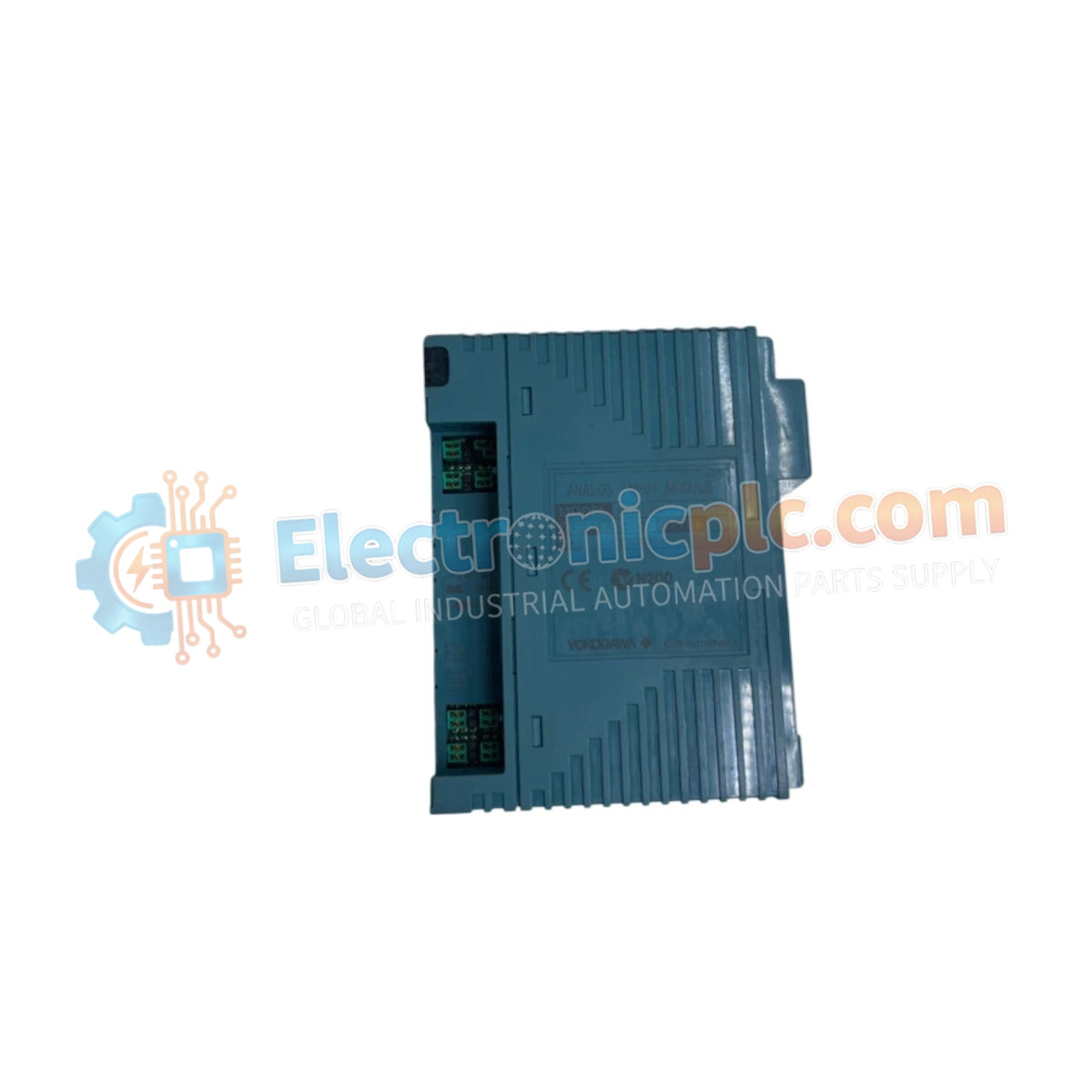
The YOKOGAWA NFAI143-500/A4500, also cataloged as the NFAI143 Analog Input Module, operates as a dedicated hardware component for 16-channel analog current signal acquisition within Yokogawa process control systems.
Availability: In stock
Reliable Worldwide Delivery
30-Day Money-Back Guarantee
Need more details? Read our fullShipping PolicyandRefund Policy.


The YOKOGAWA NFAI143-500/A4500, also cataloged as the NFAI143 Analog Input Module, operates as a dedicated hardware component for 16-channel analog current signal acquisition within Yokogawa process control systems.
The NFAI143-500/A4500 uses a standardized suffix configuration for hardware version control. The -500 designator identifies the module as a high-density input unit, while the /A4500 suffix confirms the specific compliance and calibration standard for the 4-20 mA current input range.
| Parameter | Specification |
|---|---|
| Model | NFAI143-500/A4500 |
| Brand | YOKOGAWA |
| Origin | Japan |
| Weight | 0.3 kg |
| Dimensions | Standard Yokogawa module form factor |
| Operating Temp | 0 deg C to 60 deg C |
| Power Consumption | 230 mA at 5 VDC, 540 mA at 24 VDC |
| Input Channels | 16 (isolated) |
| Input Signal Range | 4-20 mA DC |
| Accuracy | +/- 0.1 % of full scale |
| Data Update Period | 10 ms |
| Allowable Input Current | 24 mA max |
| Isolated Voltage | 1500 V AC (1 minute) |
The NFAI143-500/A4500 is engineered with galvanic isolation between the field input stage and the internal system bus. This isolation is required to prevent ground potential interference and to suppress electrical transients originating from the field wiring. The module supports direct interfacing with standard 4-20 mA DC field instruments and maintains compatibility with HART loop protocols when deployed with external loop-powered configurations, ensuring precise monitoring of process variables across all 16 independent channels.
Q: Does the NFAI143-500/A4500 provide internal loop power to field devices?
A: The module requires an external 24 VDC power source to drive the current loops. The power consumption specifications refer to the energy required for the module's internal logic and the signal conditioning circuitry.
Q: Is the module protected against accidental high-current injection?
A: Yes. The module features built-in overcurrent protection circuitry. However, input current must be kept under the 24 mA maximum limit to prevent potential hardware stress and maintain measurement accuracy within the specified +/- 0.1 % tolerance.


