My Cart
0 items
Genuine Automation Parts | Worldwide Express Delivery | 12-Month Warranty — [GET A QUOTE]

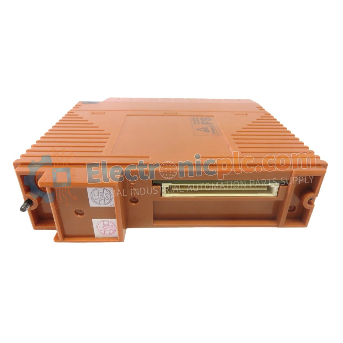
The Yokogawa NFAP135-S50/13S00, also cataloged as the NFAP135-S50 Pulse Input Module, operates as a dedicated hardware component for high-speed pulse signal acquisition and frequency measurement within industrial control platforms.
Availability: Low stock: 99 left
Reliable Worldwide Delivery
30-Day Money-Back Guarantee
Need more details? Read our fullShipping PolicyandRefund Policy.


The Yokogawa NFAP135-S50/13S00, also cataloged as the NFAP135-S50 Pulse Input Module, operates as a dedicated hardware component for high-speed pulse signal acquisition and frequency measurement within industrial control platforms.
| Parameter | Specification |
|---|---|
| Model | NFAP135-S50/13S00 |
| Brand | Yokogawa |
| Origin | Japan |
| Weight | 1.0 kg |
| Dimensions | 482 mm x 210 mm x 220 mm |
| Operating Temp | -20 deg C to +60 deg C |
| Power Consumption | System-rated load |
| Input Channels | 8 channels |
| Max Frequency | 50 MHz |
| Isolation | Channel-to-channel and system isolation |
The NFAP135-S50 utilizes high-speed comparator circuitry to perform pulse, frequency, and period measurement with a maximum input frequency of 50 MHz per channel. The design incorporates galvanic channel-to-channel isolation, which ensures that transient spikes from field pulse generators (such as encoders or flow meters) are blocked from propagating into the central processing unit or adjacent channels. This isolation barrier is engineered to maintain signal integrity in high-noise industrial environments, preventing crosstalk during simultaneous multi-channel high-speed counting operations.
Q: What input signals are supported by the NFAP135-S50?
A: The module is designed for diverse timing and motion applications, including pulse counting, frequency tracking, period measurement, time-of-flight, velocity calculation, and position monitoring.
Q: Is the module capable of 50 MHz counting on all channels simultaneously?
A: Yes, the architecture supports high-speed counting up to 50 MHz per channel; however, system-level bus capacity must be monitored when processing multiple high-frequency inputs concurrently to ensure consistent data throughput.


