My Cart
0 items
Genuine Automation Parts | Worldwide Express Delivery | 12-Month Warranty — [GET A QUOTE]

The YOKOGAWA CP451-50 S2, also cataloged as the CP451-50 Processor Module, operates as a dedicated hardware component for real-time logic execution and process data management...
Availability: Low stock: 99 left
Reliable Worldwide Delivery
30-Day Money-Back Guarantee
Need more details? Read our fullShipping PolicyandRefund Policy.


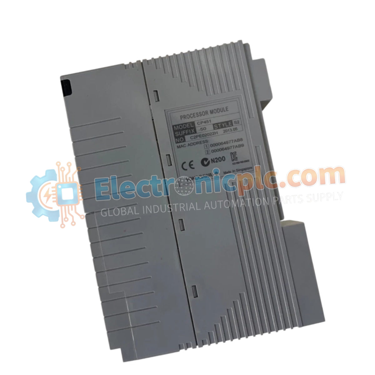
The YOKOGAWA CP451-50 S2, also cataloged as the CP451-50 Processor Module, operates as a dedicated hardware component for real-time logic execution and process data management within CENTUM DCS platforms.
| Parameter | Specification |
| Model | CP451-50 S2 |
| Brand | Yokogawa |
| Origin | USA |
| Weight | 0.6 kg |
| Dimensions | 5.1 cm x 20.3 cm x 15.2 cm |
| Operating Temp | Industrial environmental standard |
| Power Consumption | Backplane bus load dependent |
| Processing Capacity | High-speed logic control execution |
The CP451-50 S2 integrates into the control network to facilitate reliable instrumentation communication. The module is designed to interface with 4-20 mA HART loop protocol standards, allowing for the transmission of critical process parameters from field devices to the control software. To ensure signal accuracy, the architecture employs channel-to-channel isolation, which mitigates interference from electrical noise and potential differences between field loops. This implementation ensures that analog data streams remain stable, supporting the high-precision requirements of regulatory control loops within the DCS architecture.
Q: Does the CP451-50 S2 support redundant pairing for continuous control?
A: The module architecture supports redundant configurations. Ensure that both primary and standby modules share the same hardware revision and database settings to prevent synchronization errors during failover.
Q: What is the procedure if the module fails the power-on self-test?
A: A failed self-test typically indicates a hardware fault or an incomplete connection to the backplane. Inspect the connector pins for damage, verify the backplane power supply, and reseat the module firmly.
Isolate the power supply to the controller rack to prevent accidental electrical contact during installation.
Ensure that the module is inserted into the correct slot as defined by the system cabinet layout drawings.
Align the module with the guide rails and apply firm, even pressure until the backplane connectors are fully engaged.
Tighten the front panel locking screws to maintain physical stability and ground continuity with the rack chassis.
Check that all external signal cabling is securely shielded and routed away from high-voltage conduits to prevent induced interference.


