My Cart
0 items
Genuine Automation Parts | Worldwide Express Delivery | 12-Month Warranty — [GET A QUOTE]

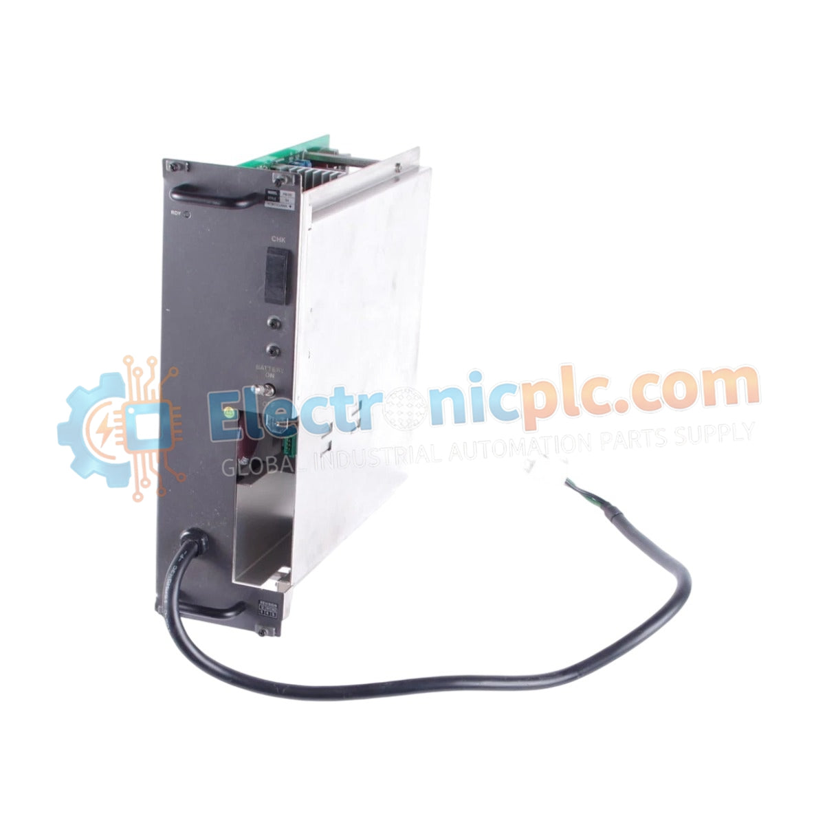
Configured for power conversion in DCS process control platforms, the YOKOGAWA PW302 S4 (PW302 Power Supply Module) provides direct physical/electrical execution.
| Parameter | Specification | ...
| Parameter | Specification |
| Model | PW302 S4 |
| Brand | YOKOGAWA |
| Origin | Japan |
| Weight | 3.6 kg |
| Dimensions | 10.2 cm x 27.9 cm x 25.4 cm |
| Operating Temp | Standard industrial ambient range |
| Power Consumption | Subject to load requirements |
| Input Voltage | 220-240 VAC |
The unit integrates specialized circuitry for channel-to-channel isolation and voltage regulation required in DCS instrumentation loops. To maintain output stability, the power supply utilizes internal feedback loops to compensate for variations in line voltage within the specified 220-240 VAC range. The output is engineered for low ripple characteristics, facilitating stable operation for sensitive analog input and output modules within the YOKOGAWA ecosystem. Proper thermal management is required, necessitating adequate cabinet ventilation to prevent internal component fatigue during continuous operation.
Q: Are there specific installation requirements for the input voltage?
A: The PW302 S4 is optimized for a 220-240 VAC input. Ensure the supply source is stable and protected by an appropriate circuit breaker to prevent input stage damage from surges or transients.
Q: How is thermal dissipation handled for this module?
A: The module relies on passive or active convection depending on the internal assembly. Ensure a minimum clearance of 50 mm around the top and bottom of the unit to facilitate airflow and maintain operating temperature within defined limits.